Let's sound a piezoelectric buzzer and speaker [STM32 Nucleo]
Let's connect a piezoelectric buzzer and speaker to an STM32 MCU (Nucleo board) and play them. This time, I used an inexpensive piezoelectric buzzer (model: LF-MB12B06). This is an application of a peripheral timer. For details, see Timer/Counter [Details of STM32's High Functional and General Purpose Timer].
Table of contents
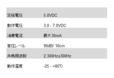
Piezoelectric buzzer specifications

A piezoelectric buzzer is a component with a built-in oscillation circuit that generates sound by resonance when a voltage according to specifications is applied. A piezoelectric speaker (sounder) is a similar component, but it does not have a built-in oscillation circuit and generates sound when an arbitrary frequency pulse is applied.
For this application, we would like to try something that can be used with both piezoelectric buzzers and piezoelectric speakers.
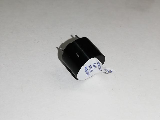
This type has polarity, and when DC voltage is connected to the positive side (longer pin leg) and GND to the negative side, the specified sound (2,300 Hz) is generated.
The voltage to be given to the buzzer is 3.3 VDC, the same as MCU voltage. A fixed voltage will produce a continuous sound, while a pulse of 3.3VDC will produce an intermittent sound.
In the case of a piezoelectric speaker, since there is no oscillation circuit, sound is not generated simply by applying a DC voltage, and a pulse of the frequency corresponding to the sound must be applied externally. If intermittent sound is desired, this pulse should be generated intermittently in a blocked state.
In this application, the piezoelectric buzzer/speaker can be used either as a piezoelectric buzzer or a piezoelectric speaker, and any frequency generated in a blocked state is given to the piezoelectric buzzer to generate sound.
Some components require a protective resistor of about 1k to be connected in series, but this one did not function with a resistor, so it was not used. Please confirm the presence or absence of a protection resistor by checking the specification sheet, etc.
Circuit of Piezoelectric buzzer with MCU
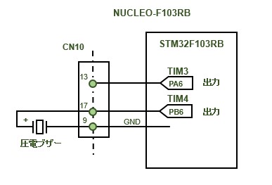
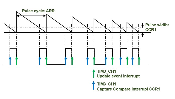
Generating pulses of fixed width at desired intervals with timer TIM3 is easy when using the PWM output function. The desired interval (frequency of pulses) is adjusted by adjusting the setting of the automatic reload register (ARR), which sets the cycle of the TIM3 timer. The width of the output pulse (length of the generated tone) is one of the PWM settings Adjust the Capture Compare Register (CCR) setting. You can set it while examining the time chart.
For a piezoelectric buzzer, it is sufficient to give the output of this TIM3 (PA6), but for a piezoelectric speaker, each pulse must be composed of even finer sound source frequencies. Therefore, I add another stage timer TIM4.
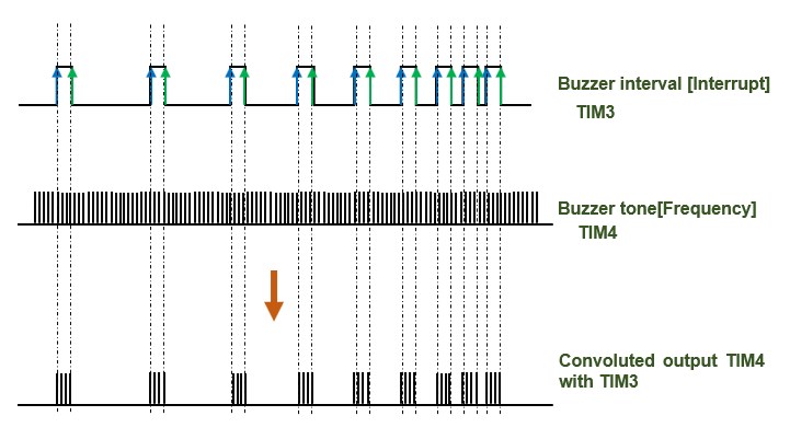
I can set timer TIM4 to output a pulse of the sound frequency, so that the fine sound pulse of timer TIM4 is output only when the pulse of timer TIM3 is output. It is like an AND circuit in a digital logic circuit.
In this case, use an interrupt synchronized with the output of timer TIM3. The update event interrupt, which occurs every count cycle, and the capture compare interrupt on the PWM output are used to generate or stop the pulse of timer TIM4.
For more details on interrupts, please refer to the section "Various interrupts [Interrupt details in STM32]".
Program Structure
This is the outline of the program. This time, only interrupts are processed.
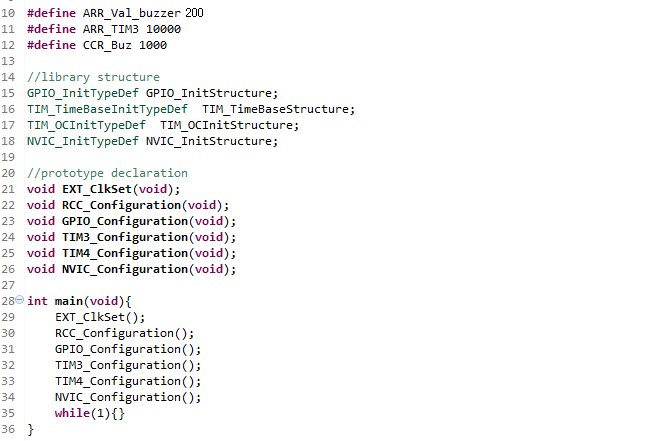
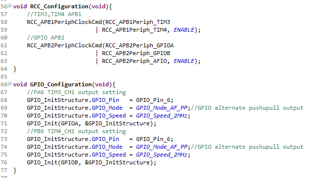
The peripherals used are TIM3 and TIM4 and the GPIO ports A and B, respectively.
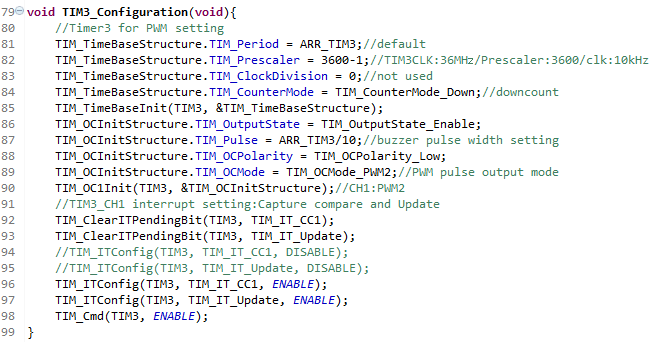
The setting of TIM3_CH1. the counter clock to TIM3_CH1 is set to 10 kHz and the cycle is set by the automatic reload register ARR_TIM3. if ARR_TIM3 is 10000, the cycle is 1 second in PWM mode.
If you want to change the automatic reload register ARR value arbitrarily during counting, set the counter mode to down counter.
The counter mode is specified as PWM mode 1 or 2. Capture compare register CCR in PWM mode is set to member TIM_Pulse. The pulse width can be adjusted with this value.
The counter is started after enabling the update event interrupt TIM_IT_Update, which occurs at each cycle update of timer TIM3_CH1, and the capture compare interrupt TIM_CC1, which occurs during capture compare of the PWM.
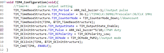
The next step is to set TIM4_CH1. This sets the sound source pulse generated by the piezoelectric speaker. This timer also specifies the PWM mode. Set the pulse period in the automatic reload register (ARR) of member TIM_Periode to the frequency corresponding to the sound source in the ARR for the piezoelectric speaker. Set the pulse width in the capture compare register (CCR) of member TIM_Pulse. Normally, a duty ratio of 50% ON/OFF ratio is sufficient.
It is set to output 2.5 kHz pulses (duty ratio 50%) in PWM mode.
Since the pulse setting of TIM4 is not necessary for a piezoelectric buzzer with a built-in oscillation circuit, it is better to set a larger pulse width (duty ratio) in the PWM mode capture compare register to get closer to the original sound.
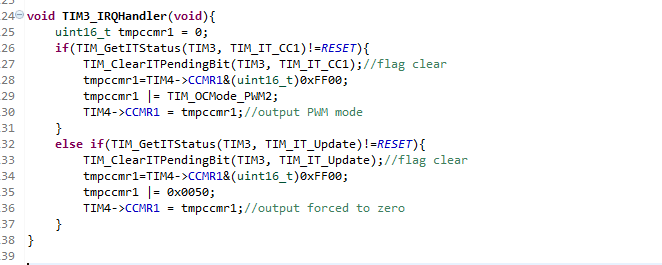
Finally, the interrupts are set up so that TIM4_CH1 starts counting in PWM mode via the PWM output capture compare interrupt of TIM3_CH1. The update event interrupt generated every TIM3_CH1 count cycle forces TIM4_CH1 to zero output. Here the registers are operated directly instead of using the appropriate firmware functions.
The pulses generated by the configured TIM3 and TIM4 are shown below, with TIM4 synchronized to the pulse of TIM3. In this application example, the TIM3 pulse is fixed, but you can develop it into something that changes the interval (ARR) and pulse width (CCR) during operation.
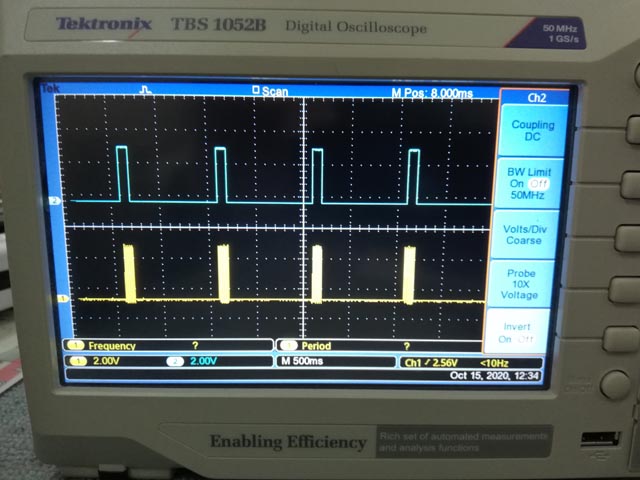
The actual sound of the piezoelectric buzzer. 50% PWM output duty ratio of TIM4 gives a faint sound, so I set the duty ratio to about 90%, which is closer to the original sound.
In the case of a piezoelectric speaker without a built-in oscillation circuit, changing the pulse frequency using TIM4 will change the tone, so it would be interesting to combine it with a piezoelectric speaker with a different sound length by adjusting the pulse width using PWM of TIM3.
On the necessity of an oscilloscope:
Especially when dealing with pulses, as in this application, it is necessary to check with an oscilloscope to confirm that the application is working as expected. Only by checking the actual waveforms with an oscilloscope can you identify any defects or areas for improvement in the program. Oscilloscopes nowadays are not as expensive as they used to be, but are sold at prices that even ordinary people can afford, depending on the performance of the frequency band they handle, so they are measurement devices that should be owned along with Multi-meters.
About Register Operation:
If there is a firmware function available in the SPL (Standard Peripheral Library), you can use it, but there may be cases where you want to perform a small operation and there is no appropriate function. In such cases, you can directly operate registers. In the case of SPL, the firmware functions are relatively simple, so it is easy to understand the register operations in the functions and relatively easy to apply them. In that sense, I think SPL is suitable for learning MCUs.