Let's clarify the mechanism of the complementary filter [acceleration/gyro sensor]
Complementary filters are often used to combine accelerometers and gyroscopes, but there are few explanations on the details of these filters. It is interesting to know how the complementary filter equation is derived and what the equation means. I will explain the calculation process to show that there is a deep meaning in a relatively simple formula.
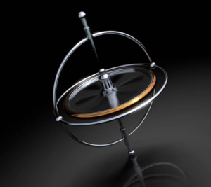
Accelerometer and gyro-sensors are devices that detect information on the motion and rotation of an object, but each has its own disadvantages and advantages, especially in obtaining the attitude position.
Accelerometer is a sensor that detects motion, and to obtain the attitude position, the tilt angle of each axis can be calculated from the gravity applied to the x, y, and z axes.
The gyro sensor can detect angular velocity in each of the three axes (x, y, and z), which can be integrated in the program to calculate the movement angle.
Each could be used independently to obtain an object's attitude position, however, accelerometers have sensitive outputs and contain fine noise, in addition to the addition of non-gravitational components when there is motion. Gyro-sensors integrate the detected angular velocity, so the error component also accumulates, causing drift (offset).
One way to overcome the disadvantages of the accelerometer and gyro sensor, and to obtain a stable attitude by only using the best of their advantages, is to use a complementary filter.
Table of contents
Complementary filter configuration

The complementary filter is shown in the block diagram below.
Accelerometer passes a low-pass filter (LPF) because they want information in the low-frequency range with noise components removed.
A gyro sensor can cancel the offset due to drift by passing it through a high-pass filter (HPF) to remove the accumulated drift component.
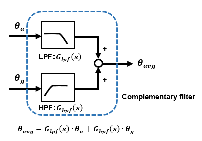
The term "complementary filter" is derived from the fact that the accelerometer or gyro sensor is not only filtered individually, but also combined with each other to combine the best of both worlds.
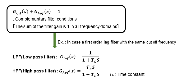
The LPF and HPF used in the complementary filter have a condition: the sum of the filter gains must be 1 at any given frequency.
It may seem that you can simply pass a low-pass filter (LPF) through a single accelerometer or a high-pass filter (HPF) through a single gyro sensor without bothering to use a complementary filter, but in these cases, the phase delay caused by the filter or the signal information gain changes between input and output, the advantage of this complementary filter is that it uses the advantages of the two sensors to obtain the ideal output.
Frequency response of the complementary filter
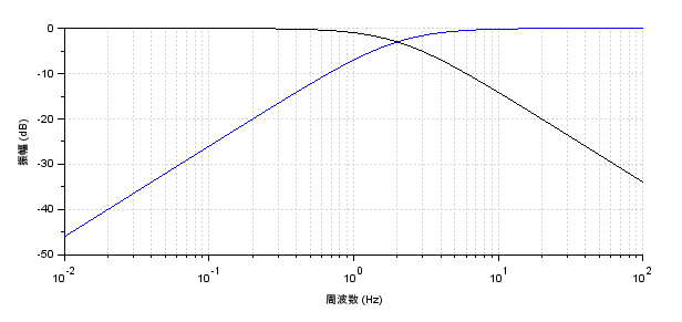
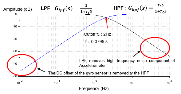
The following figure shows the characteristics of the LPF and HPF of the complementary filter when the cutoff frequency is set to 2Hz, expressed as a Bode diagram in the frequency domain. The vertical axis represents the gain in dB (decibel), and under this condition, the LPF and HPF gains add up to 1 over the entire range.
The LPF removes high-frequency components above the cutoff frequency fc, so only the low-frequency portion of the information from the acceleration sensor remains.
The HPF removes low-frequency components below the cutoff frequency fc. Since the HPF removes low-frequency components below the cutoff frequency fc, offsets due to slow drift of the gyro sensor are removed.
If the cutoff frequency fc is set to 2 Hz, the information from the gyro sensor will be almost dominant. In the end, we can fine-tune the fc by watching the output.
Calculation process of the complementary filter
The complementary filter can be used if you know only the resulting formula, but if you do not know the meaning of the formula, you will have to determine the coefficients and other parameter values by guesswork.
If you are going to use a complementary filter, you will still want to understand the equation to some extent.
The following calculation process does not use any difficult theory, but requires at least a basic knowledge of classical control theory to understand. Please refer to "Fundamentals for Feedback Control realized by MCU[Preparation] and [Analysis]" on this website.
This section can be understood if you are familiar with concepts such as first-order delay filters, Laplace transforms, etc.
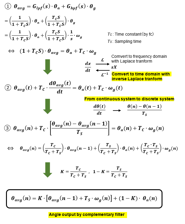
Finally, I have derived an expression for the complementary filter that we often see. This is for a first-order filter. Now you know what the weighting factor K means.
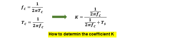
The coefficient K is determined by the cutoff frequency fc and the sampling time TS.
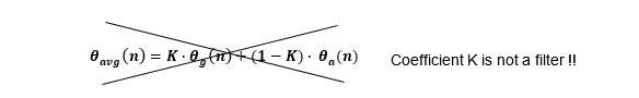
Some commonly available complementary filter information interprets the outputs of the accelerometer and gyro sensor by applying a coefficient K as a weight, but this does not make sense.
Looking at the results alone, you can see that the complementary filter formula is relatively simple in form, but you can understand that it actually contains so much meaning. If you understand the content of the formula without being a black box, you will be able to use it with confidence. The idea of the complementary filter is genius and even impressive.