Microcontroller Ethernet-enabled system design [STM32Nucleo]
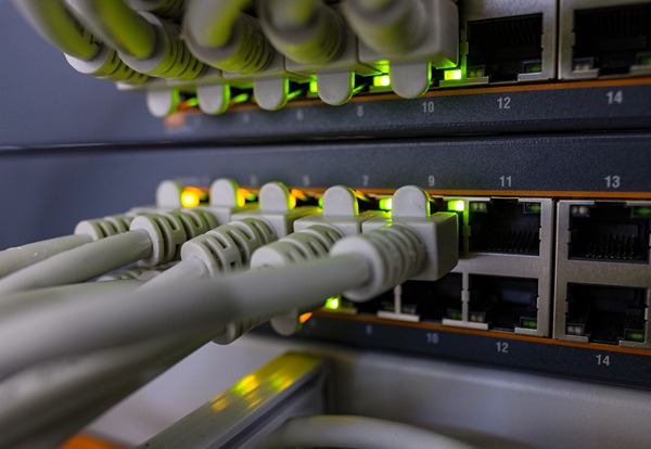
Table of contents
Fundamentals for connecting MCUs to the Internet
The IoT, which is used by connecting to a network, has been spreading to embedded devices as well. While WiFi network connections are common for home appliances such as televisions and other consumer products such as smartphones, Ethernet, a wired communication method, is used for products for industrial equipment that require operational stability and security.
In this article, I will explain how to support Ethernet IoT by applying the external Ethernet-enabled LAN controller W5500 to a general-purpose MCU(Nucleo-F103RB) that you have been familiar with. The target is the STM32, but it is an easy way to support any model by customizing the interface (SPI communication) between the MCU and the LAN controller.
Here, I omit explanations of IP addresses and other network-related matters.
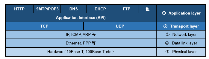
Network hierarchy

Although devices and equipment of various standards are connected to the network, the network standards are standardized by the OSC reference model below, so any device or equipment can communicate with any other device or equipment as long as it is based on the common standards.
Ethernet is one of the most popular wired LAN standards and is defined by IEEE802.3.
According to the standard, a communication system is to be built from the LAN cable at the physical layer to, for example, the HTTP application layer using a web browser. The data link layer is usually hardware-based, and the rest is software-based.
Selecting a LAN Controller for Ethernet Support
There are three main types of MCUs with respect to Ethernet communication, which can be categorized as follows.
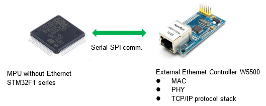
- General-purpose MCU (without Ethernet controller)
- MCU with built-in MAC device
- MCU with built-in PHY device
The first general-purpose MCU is not equipped with an Ethernet controller, so a MAC/PHY device controller is externally attached to it, and SPI, I2C, and other general-purpose buses are used as interfaces for communication. The Nucleo-F103RB MCU we will be dealing with this time falls into this category.
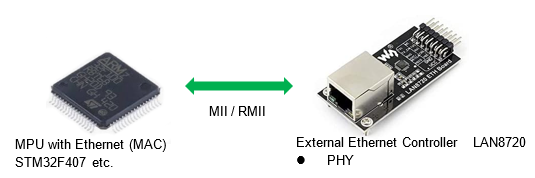
The second MCU has a built-in Ethernet MAC device, for example, the STM32F407. It communicates with the MCU's built-in MAC device using a method called MII/RMII with an external PHY device controller.
The third MCU incorporates the device MAC and PHY required for Ethernet, and the only additional component is an RJ-45 with built-in pulse transformer.
The following is a list of commonly used and easily obtainable controllers that can be combined with MCUs to make them Ethernet-compatible.
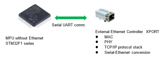
XPORT
Even if you have no knowledge of Ethernet, you can use a controller with a general-purpose serial communication interface like the ESP32 used for WiFi, just like serial communication.
It can be selected as the simplest IoT-enabled controller. The advantage is that it can be externally attached to existing devices that support only serial communication, but the disadvantage is that it is not highly versatile because it follows the driver provided by the manufacturer.
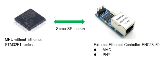
ENC28J60 Lan controller
The ENC28J60 controller can be made Ethernet-compatible even with MCUs that do not have an Ethernet controller, as long as they have SPI communication.
Since the TCP/IP protocol stack must be built in by yourself, the STM32F1 series seems to be very difficult to implement with few examples. If you do not want to take the time to understand the contents of the selected TCP/IP protocol stack, the following W5500 is recommended.
W5500 Lan controller
As in the case of the ENC28J60 controller, it is applicable to MCUs without an Ethernet controller that have SPI communication. The major difference between the two is that the W5500 has a TCP/IP protocol stack built into the hardware, which eliminates the hassle of installing a TCP/IP protocol stack and provides a stable connection.
Therefore, in addition to being usable without knowledge of the TCP/IP protocol stack, another major advantage is that it can be implemented in MCU with small memory due to its low software load.
The Nucleo-F103RB is a well-balanced controller that requires few external components for the STM32 in the Nucleo-F103RB and can be expanded to socket communication using the TCP protocol and communication from a browser using the higher-level HTTP protocol.
LAN8720 Lan controller
Controllers such as LAN8720 and DP83848, which only have PHY devices for those with built-in Ethernet-compatible MACs like the STM32F407 , can better utilize MCU's functions.
Controllers such as LAN8720 and DP83848, which only have PHY devices for those with built-in Ethernet-compatible MACs like the STM32F407, can better utilize the microcontroller's functions.
Using the STM32CubeIDE development environment, the TCP/IP protocol (LwIP) can be easily incorporated and even the transport layer TCP and UDP protocols can be implemented by using the automatic generation function at the development project creation stage.
When designing a product for network equipment from the beginning, it is probably a good idea to select MCU with a built-in network.
I checked the specifications of the W5500 model as an Arduino Ethernet shield (including compatible products), thinking that it would be good if it could be used with the Nucleo board, but the important interface part, the SPI communication terminal, is not compatible with the Nucleo, so it cannot be used.
Controller W5500 with built-in TCP/IP protocol stack
To make the STM32F1 series MCUs without an Ethernet controller Ethernet-compatible, the W5500 or ENC28J60 should be considered for versatility.
The W5500, which has a TCP/IP protocol stack built into the hardware, is particularly good as a network specification, and can easily be used to network a microcontroller, then I will choose this one.
The TCP/IP protocol stack conforms to the standard, so there is little need to understand the internal details and it can be dismissed as a pre-existing module.
NUCLEO-F103RB and W5500 module
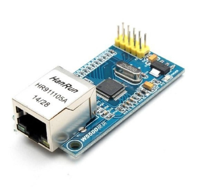
To connect the Nucleo-F103RB to the network with an external W5500, here we use a commercial W5500 board. The boards are inexpensive and have minimal peripherals, but many of them do not have a MAC address.
EEPROM or other memory to hold the MAC address is required for product development.
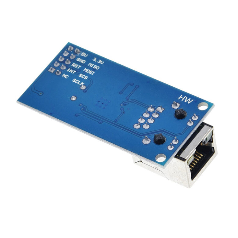
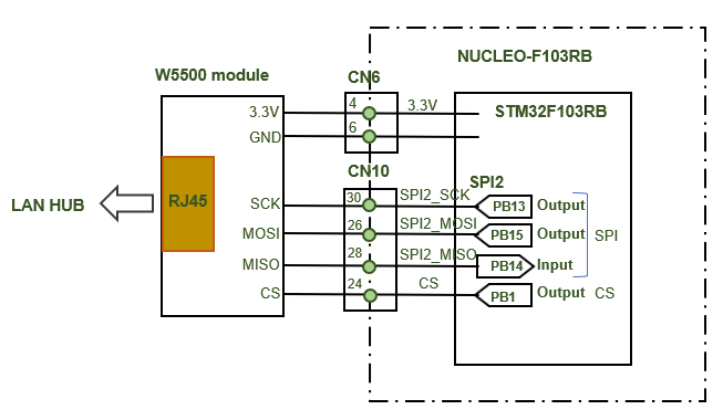
The only connections to the Nucleo are the power supply and the SPI communication section if interrupts and resets are not used. However, the W5500 does not have a power-on reset, so a hardware reset should be used especially in the case of commercialization to ensure a reliable reset. In this case, SPI2 is used, so the connection is as shown in the figure below.
About MAC Addresses:.
A MAC address is required to use Ethernet, but the LAN controller used does not have a MAC address. If you just want to check the operation on the Internet, there is no problem, but if you want to market the product as a product, you need to register a MAC address specific to each product in advance.
STM32 and W5500 driver
The W5500 communicates by operating registers inside the IC via SPI communication. The details of the registers are described in the W5500 datasheet, but for programming, the drivers provided by the manufacturer are registered as a library (ioLibrary_BSD), and functions are called as needed.
What is W5500 driver?
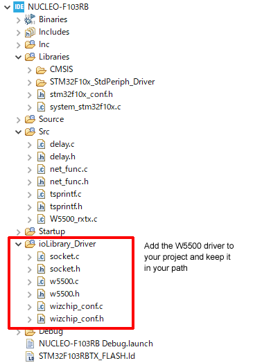
The file wizchip_conf.c/wizchip_conf.h is a collection of functions that interface SPI communication with the STM32. This file specifies the controller IC chip (W5500) to be used, register addresses, etc. The file wizchip_conf.c/wizchip_conf.h contains the functions for SPI communication interface with the STM32. It is necessary to modify some parts of the file when customizing the interface with MCU.
w5500.c/w5500.h defines and summarizes the send/receive functions with the microcontroller used in controller W5500.
socket.c/socket.h is a set of functions used for TCP socket communication. The functions conform to Berkeley Sockets (BSD sockets).
It would be good to register these as the minimum drivers in the ioLibrary_driver folder and add others as needed, such as those related to DHCP.
SPI communication and driver customization for W5500
The W5500 LAN controller has a common register block for writing/reading operations, IP addresses and other parameters, protocol specifications, and other specifications, and a socket register block for use in socket communications.
The register details are explained in the W5500's instruction manual, which allows for fairly detailed settings, but only some of them are used in general applications.
To operate these register blocks, SPI communication is used as an interface to MCU, so if this part can be established, it is almost done.
Only a small part of the driver interface file (wizchip_func.c) needs to be modified to STM32 specifications. In actual programming, the functions defined in the driver can be used, so once you understand the points, it does not take much time and effort.
I think it is a good idea to follow the functions in the driver in order to see how the registers are actually manipulated, while looking at the instruction manual at least once.
SPI frame format for W5500
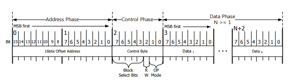
The frame format for spi communication in the W5500 consists of three phases shown in the figure below, with a block of one byte (8 bits) each. There is an address phase for the upper and lower 2 bytes, a control phase of 1 byte, and a data phase.
Driver Customization
This is a customization to tie SPI-related functions (chip select, send/receive) defined in the STM32 to the W5500 driver.
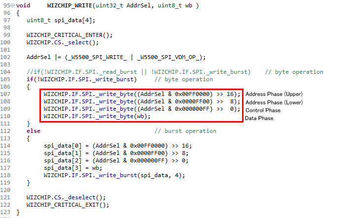
In the SPI interface (wizchip_conf.c), additionally register the part circled in red below. Chip select function SPI_CS1_Select()/ SPI_CS1_Deselect() is self-made for STM32Nucleo.
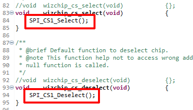
Add and register your own send/receive function SPI_Send_Receive() in the same way.
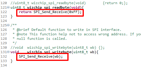
If the contents are different, the SPI send/receive function additionally defined in the above figure is tied to the driver-defined function as shown in the figure below.
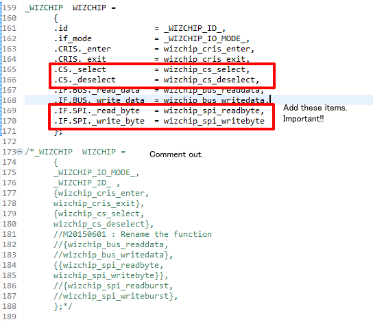
In fact, this is the only important part to add or rewrite to the driver. In addition, you only need to modify the file paths to be included, which will result in an error during the build process.
Don't forget to include a file defining your own SPI-related functions in the header file of the SPI interface (wizchip_conf.c) so that it can be linked.
- In wizchip_conf.h #include "W5500/w5500.h" modified to "W5500.h
- Add #include "net_func.h" (self-made function file) in wizchip_conf.h
- Corrected #include "Ethernet/wizchip_h.h" to "wizchip_h.h" in w5500.h
- Corrected #include "Ethernet/wizchip_h.h" to "wizchip_h.h" in socket.h
In the function wizchip_init() defined in the SPI interface (wizchip_conf.c), the variable i is declared as signed int8_t i.
Please change it to unsigned uint8_t i. if you do not change it, you will get various warnings.
W5500 Initial Settings
Once the interface with SPI communication is ready, the actual programming involves initialization using functions defined in the driver.
Initial Setup Flow
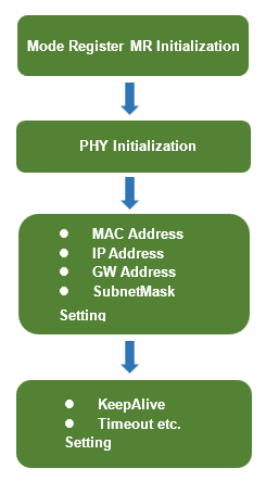
The initialization flowchart is summarized in W5500_ini() in the program as follows. The functions for register manipulation are defined in the driver header file W5500.h.
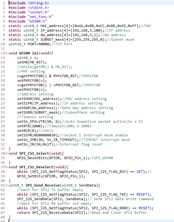
Initialization Operation Details
The W5500 can be configured for multicast and other advanced settings, but here we will initialize with simple basic single-cast settings.
Reset register (MR_RST) is issued to register PHY initialization, source (server side) MAC address, IP address, KeepAlive, timeout, etc.
① Initialization of mode register MR
Performs a reset by setting up the RST bit in the MR register.
Execution function: setMR(MR_RST)
② PHY initialization
Reset PHY settings to default values
Execution Function
v=getPHYCFGR() & PHYCFGR_RST;
setPHYCFGR(v);
v=getPHYCFGR() | ~PHYCFGR_RST;
setPHYCFGR(v);
The PHY mode can be set in detail in the registers, but here the circuit settings for pins 43, 44, and 45 (all Hi) are given priority, and standard auto-negotiation is the default.
③ Setting of MAC address, IP address, GW address, and subnet mask
setSHAR(MAC_address);//MAC address
setSIPR(IP_address); //IP address
setGAR(GW_address); //Gateway
setSUBR(SUBNET_mask);//Subnetmask
WIZCHIP_WRITE_BUF() is used for writing because it handles array data such as IP addresses. When commercializing the product, the data is stored in memory such as EEPROM so that it can be rewritten except for the MAC address.
④ KeepAlive, timeout settings
setSn_KPALVTR(SN, 6);//KeepAlive
setRTR(2000);//Timuout
setRCR(8);//Timeout retry count
setSIMR(0b00000010) ;//Socket 1 interrupt mask enabled;
setSn_IMR(SN, Sn_IR_TIMEOUT);//Timeout interrupt mask
setSn_IR(SN,0x1f);//Interrupt flag reset
These are not required, but should be standard settings depending on the usage situation. Details of the settings are described in the W5500 datasheet.
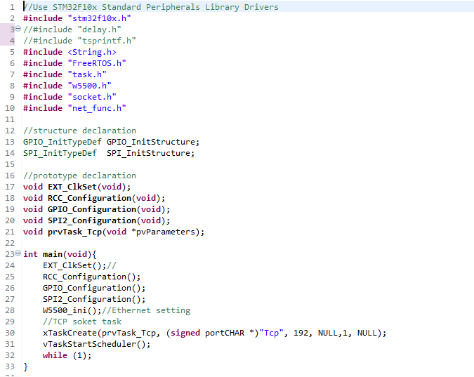
Whole Program Description
After completing the initial setup so far, the communication environment up to the network layer is ready. The full program is as follows
The initialization function W5500_ini(), net-related homebrew functions, etc., are separately compiled in the module net_func.c and its header files are included.
Actual operation check
Addresses vary depending on the operating environment and should be adjusted to the actual one.
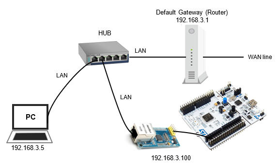
Nucleo-F103RB + W5500 connected to LAN
When the program is run, it can connect to a LAN with a network address belonging to the configured IP address.
Here the network address is 192.168.3 and the IP address is set to 192.168.3.100.
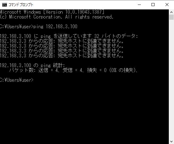
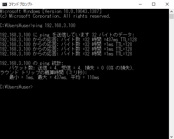
Connection check by PING command
Run the "ping" command from the PC command prompt screen to see if it is recognized in the network. Check the response when typing "ping 192.168.3.100".
A screen like the one below indicates that the ping is not passing through due to an incomplete connection for some reason.
In such cases, there is usually some reason, such as an incomplete cable or a different IP address than the one you have set.
If the ping response is like this on the first connection immediately after programming, there may be some flaw in the program, and you will find the cause of the bug. It is especially important to check the operation related to spi communication and the path of the driver related files. Once it works, it is fine.
If the program functions properly, the screen below will appear. In this state, the ping has passed, indicating that it has successfully joined the network.
Since the ping command is in the ICMP protocol, the communication system is established up to the network layer of the OSI reference model.
The ping command alone cannot do any work other than checking communications, but once a network has been established up to this point, a web server can be created and accessed from a browser using the upper-level TCP protocol for socket communications or the higher-level HTTP protocol.
This time, the IP address is the fixed value "192.168.3.100" stored in memory. Although not explained here, if the DHCP function is installed, an IP address automatically assigned by the DHCP server can be used.
In the next issue, I will implement TCP, the upper-level protocol, to realize socket communication.
When trying to connect to the Internet for the first time, it is difficult to get a ping to pass because of the hardware involved, but once the ping passes, the Internet communication is almost complete. Once this point is reached, software can be used to develop socket communication, web servers, and so on.