Build a pulse-following positioning servo control system using Microcontroller

So far, I have realized positioning motion control using the acceleration command method as a method to follow a motor position trajectory created in advance, and confirmed the effectiveness of this operation.
Many actual motor positioning servo systems give pulses as positioning commands. Therefore, in this article, I will try to realize a positioning system using MCU that uses pulses generated by an external encoder as a command value and follows the motion of the encoder.
From the point where it tracks the pulse, it will only operate for the pulses you give it, like a stepper motor.
Table of contents
General positioning servo system

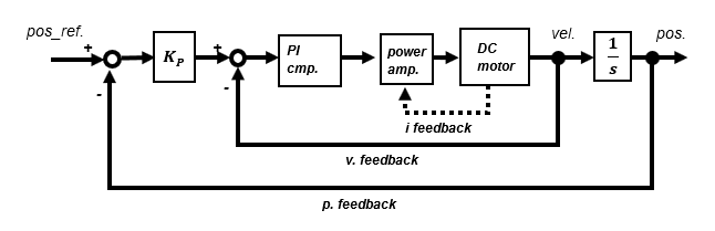
Block diagram of a typical motor positioning servo system. If the power amplifier is a current command type, there is a current feedback loop in the innermost part, and a current command is given to the motor. In the case of a voltage command type, the voltage command value is given in open control.
Motor positioning servo systems generally use speed control feedback to first stabilize the motor speed and then provide an external position feedback loop.
Positioning servo applying High-gain feedback method
"High-gain feedback method" is used for speed control, which can be easily realized with MCU program and is effective in suppressing disturbances.
To develop into a position control system, a position feedback loop is provided outside the speed control system.
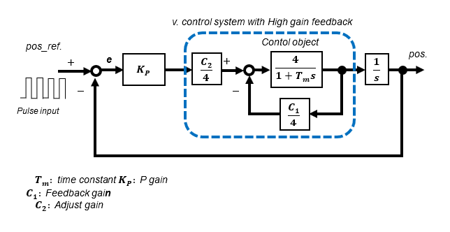
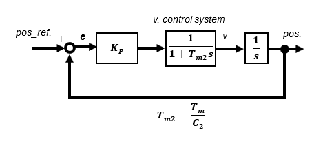
In the High-gain feedback method, the speed control system can be approximated as a 1st-order lag system. The reason why only proportional gain KP is used as a compensator for position control is that the transfer function from input to output is a 2nd-order lag system.
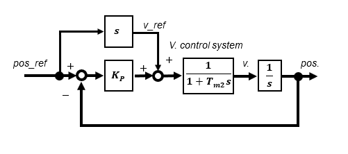
If an arbitrary pulse is given externally, there is some difficulty, but if the trajectory of the position target value is known in advance, a speed command value can be created, so adding this as a feedforward term improves response even more.
Determination of position compensator gain
The transfer function between input and output is a 2nd-order lag system as follows Since the time constant Tm2 is known, the gain KP is uniquely determined by specifying only the damping ratio ζ.
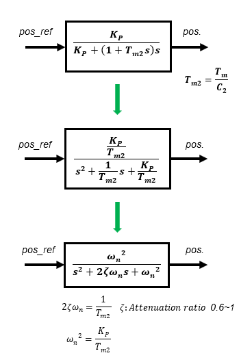
For example, if the time constant Tm2 is 25ms and the damping ratio ζ is set to 1, ωn is set to 20 and KP is set to 10.
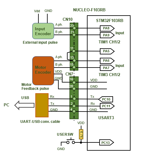
Actual circuit
The motor position and the position command value from external input pulses are obtained by counting up and down according to the encoder interface mode of the timer.
User SW is used to reset/preset position information. If it is specified around the middle value of the up-down counter when reset, it can prevent malfunctions due to counter overflow or underflow during operation.
Simulation and actual operation
① Simulation
First, the customary simulations were performed in Microsoft Excel. I verify the case where the High-gain feedback gains C1 and C2 are 2 and 3, respectively.
Since the transfer function between input and output is a 2nd-order lag system, the position gain KP is 15 when the damping ratio ζ is specified as 1.
Under these conditions, the characteristics of the 2nd-order lag system are well represented. When the input command value is changing in a ramp-like manner, the output changes with a slight steady deviation, and when it reaches a constant value, it is servo-tracking with no steady deviation. This is as per the final value theorem of control theory.
If the High-gain feedback gains C1 and C2 are raised too high, speed tracking and disturbance suppression are improved, but they become too sensitive and oscillatory. For position servos, a smaller gain is sufficient.
In the case of a 2nd-order lag system, a steady-state deviation remains at the ramp input, but by adding an integral compensator in the position compensator to increase the order of the transfer function, the steady-state deviation theoretically (final value theorem) converges to zero. As described in the previous section, "Build a positioning control servo system of DC motor using Microcontroller for practical use" if the orbit is known, adding feedforward terms for acceleration and speed as command values will enable the system to follow the orbit without delay.
② Actual measurement by actual equipment
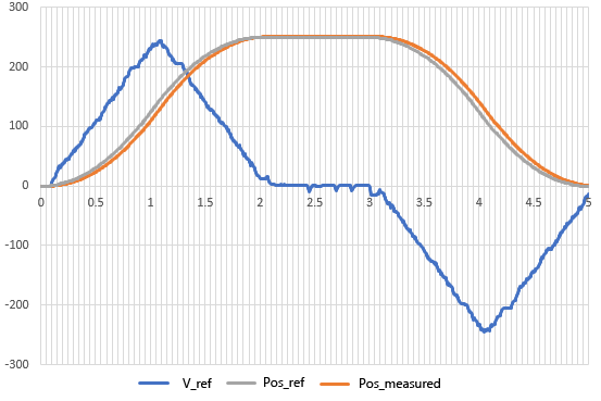
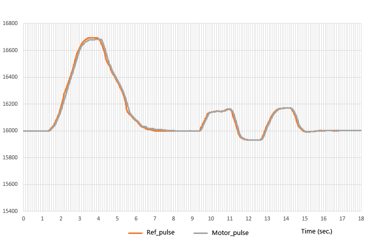
This is the actual measured value of the operation by the actual machine. When the encoder axis is turned manually, the so-called pulse synchronous operation follows the pulses generated in accordance with the axis movement.
In both forward and reverse rotation, the motor position can be seen to track the arbitrarily given pulses, i.e., the movement of the encoder axis.
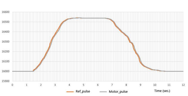
Even in the case of a somewhat complex input pattern, it is well tracked.
Checking the position command pulse (upper row) and motor position pulse (lower row) values from the encoder on the serial monitor, you can see that the motor position pulse follows the command pulse.
A basic DC motor positioning servo system can be easily realized by adding a feedback loop for position control outside of the stable speed control and using the position deviation through the position compensator gain KP as a speed command. The motor moves by the amount of arbitrary pulses given as a position command, exactly the same as a stepping motor.
In the movie, you can see how easily the system follows the pulses given externally, but there is no trial-and-error adjustment part, and the system is based on control theory. This is an example of how a seemingly difficult technology can be made simple if the fundamentals of control are well understood. The real appeal of feedback control lies in the fact that even a non-hobby object such as a LEGO motor, which is not highly precise, can be driven in an advanced manner depending on the theory and programming.