Build a positioning control servo system of DC motor using Microcontroller for practical use

In the previous issue, I applied the PI control method, High-gain feedback method, and 2-degrees of freedom robust method introduced on this site to realize practical speed servo operation with MCU using the LEGO EV3 motor as a theme, and verified the characteristics of each method on an actual device.
This time, as a further development of the speed servo, I would like to verify the position servo (position tracking control), which controls the rotational position of a motor, using actual equipment.
Table of contents
Positioning servo (acceleration command method)

If a High-gain feedback method or 2-degree of freedom robust control is applied to a speed control system to enable it to respond according to command values, it is easy to develop it into a positioning servo system.
In this section, I will verify the acceleration command method, which allows the gain that determines the response of a positioning servo system to be selected almost uniquely, and apply it to an actual machine to verify its effectiveness. The acceleration command method is explained in detail in "Fundamentals of Feedback Control using Microcontroller[Advanced]".
In this method, not only the position of the target orbit to be set but also the velocity and acceleration are decomposed in advance and given as command values.
To determine the gain Kp and Kv, refer to the 2nd-order lag characteristics explained in "Fundamentals of Feedback Control using Microcontroller [Analysis]". By setting the gain appropriately, the position deviation converges to zero and a so-called positioning servo can be realized.

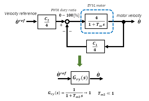
The above equation is valid because robust control is applied to the velocity system and the velocity command value θ'ref ≈ velocity θ', which means that the acceleration command value θ"ref ≈ acceleration θ".
If the initial error is converged in the characteristics of the 2nd-order lag system by appropriately set gains Kv and Kp, the position θ will follow the target value θo without delay. For details, please refer to "Positioning Tracking Control (Acceleration Command Method)" in "Fundamentals of Feedback Control using Microcontroller [Advanced].
This time, a High-gain feedback method is used for the speed control system to achieve simple robust control.
Application to actual equipment
The trapezoidal velocity pattern is the simplest for the command value, so this is used in this case. If you use floating point in your program, you can define acceleration curves using the sin function, etc., to create smoother patterns.
To create a command value, use Microsoft Excel to calculate the value for each cycle time, as shown in the figure below.
In actual programming, the same operations as those in Excel can be substituted into the acceleration, velocity, and position command value arrays, respectively. The number of arrays to be prepared is 1000 for each, since the cycle time is set to 5ms in the example below (5s/5ms).
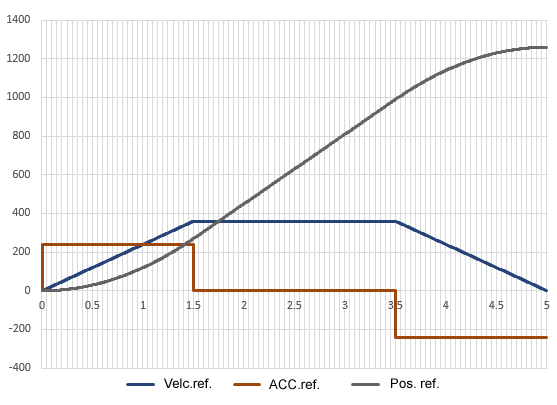
- Peak speed : 360 p/s
- Acceleration/deceleration period :1.5s
- Trapezoidal pattern with a steady-state period : 2.0s
Reference value creation is at the level of high school math function problems. It is a review of the basic concepts of derivatives and integrals and linear and quadratic functions. It's a bit of a brain exercise, so give it a try.
Velocity and position data for feedback and actual machine measurements are taken into Nucleo from encoder pulses, but velocity and position are measured by separate timers and counters.
Actual Operation
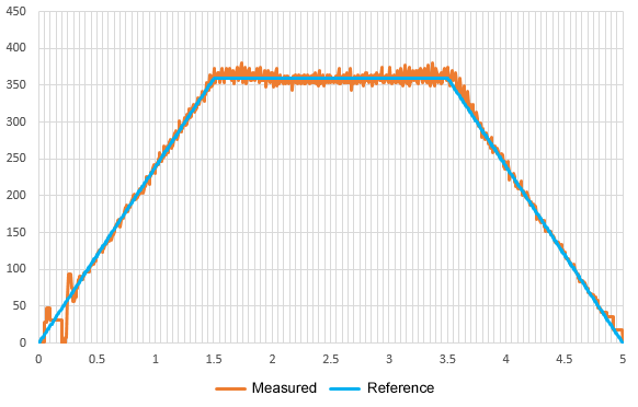
Command and measured values of speed change with no disturbance load. The speed change is inevitably slightly disturbed at startup, but this may be due to the high-gain feedback. Since the encoder resolution is extremely coarse and the arithmetic operations are integer, it may be necessary to do something more to make it work as ideal, especially at low speeds, even though some efforts have been made.
Since this is the actual speed measured by the positioning servo, slight pulsation at steady speed is not a problem.
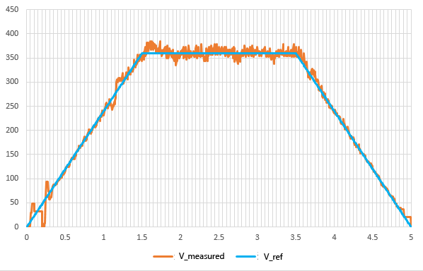
This is the speed when a disturbance load is applied every 0.5s. There is a slight disturbance affect, but it is almost stable due to the high gain feedback.
Actual motor travel position. It can be seen that there is no deviation between the position command value and the actual measured value, and the motor tracks without delay. Even when a disturbance load is applied, there is almost no affect on the position.
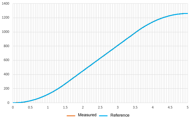
The LEGO EV3L motor has a built-in encoder with 180 pulses per revolution. This command value is for a final arrival pulse of 1260 pulses in exactly 7 revolutions.
Movie 1 Serial Monitor
The upper row shows the speed and the lower row shows the position, reaching the set position 1260 after 5 seconds of trapezoidal acceleration/deceleration.
Movie 2: LEGO EV3L Motor 7 rotation positioning
The actuator has stopped exactly 7 revolutions (1260 pulse minutes) after starting.
It was confirmed that even a simple encoder like the LEGO EV3L motor can be developed into a positioning servo with advanced robust control to achieve highly accurate position tracking control.
The hardware is a very ordinary combination of MCU and a voltage-controlled driver, but motion control that applies full-scale theory can be easily realized.
I have introduced applications of control theory that do not require special hardware, but can be applied by anyone. Although I have used motion control using motors as an example, it would be interesting to see how it can be used for other applications.
In order to operate a control system such as motion control by programming MCU, etc., it is first necessary to check the operation by simulation and determine whether it can be realized as per theory. The quickest way to realize this is to use simulation software such as Scilab to check the operation in the theoretical stage, and then use Excel or other software to simulate the discrete system for programming.
The key part of even the most sophisticated control theory is only a few lines of equations in an actual program of hundreds of lines. However, these few lines of description can transform the original characteristics into something completely sophisticated. The interesting thing about feedback control is that it transforms a physical object into something like chemistry. Don't you think it's interesting?