STM32Nucleo board recommended for learning while electronics work
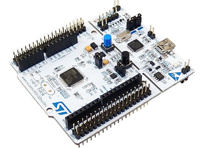
Table of contents
Why use Nucleo boards with STM32 microcontrollers for teaching materials?

The shortest way to learn MCUs is to actually operate a MCU and check its operation by yourself. If the operating environment is the same as the one explained on this site, the process of trial and error for implementation, which is the most difficult and time-consuming for beginners in particular, can be greatly shortened, and learning can begin immediately on the actual device, allowing you to learn MCU operation in the shortest possible time.
The board used as teaching material on this site will be the NUCLEO-F103RB with the ARM Cortex-M3 core STM32F103RB. Other STM32 series MCUs are also acceptable, but they need to be customized according to the specifications of MCU, and beginners may fail there. Especially for those who are new to MCUs, I recommend that you learn by using the instructional boards introduced on this site. By the time you become familiar with the operation of the microcontroller, you will have acquired skills that can be easily ported to STM32 MCUs of other specifications.
For boards with STM32 MCUs other than the NUCLEO-F103RB, the same SPL (Standard Peripheral Library) can be used, especially for the STM32F1 series MCUs, because they are compatible, and you can select an equivalent MPU when creating your project. It is relatively easy to use, although the symbols specified in the SPL, operating clock, and other settings need to be customized somewhat to match the board.
If the STM32 microcontroller is not of the STM32F1 series, for example, the STM32F4 series with a Cortex-M4 core requires the use of an F4 series-specific SPL, which is not compatible with the F1 series SPL used on this site, so it cannot be used as is. After you understand the basics with the STM32F1 series MCUs, you will be able to use them because porting is not that difficult. However, if you are not familiar with them, I recommend that you use the F1 series, especially the NUCLEO-F103RB, which has the same environment as our site.
The STM32F4 is a higher-end model of the STM32F1 (Cortex-M3) with Cortex-M4, higher operating clock speed, hardware floating-point arithmetic, and higher performance and functionality, but for beginners' learning purposes, the STM32F1 is not too much or not enough at all. Although the STM32F4 can be made to function with SPL, which I encourage for learning purposes on this site, it is better to use the HAL (Hardware Abstraction Layer) library, which is the latest library available, to take advantage of its performance and functionality, so the F1 It is recommended that you become familiar with the series before selecting a higher-end model.
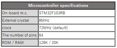
The educational material board contains the STM32F103RB as the target MCU. An 8 MHz crystal oscillator is mounted as an external clock oscillation source, and the system clock is set at 72 MHz. This processing speed is sufficient for normal applications.
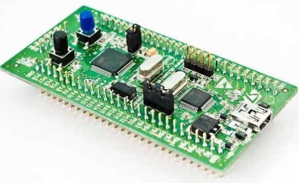
The Nucleo board has an On-board ST-LINK/V2-1 debugger, so you can start learning with only a USB cable.
This board is the NUCLEO series from ST Electronics with STM32F1 MCU. NUCLEO series features IO pin header compatible with Arduino Uno Rev.3, which is very popular in electronic construction, in addition to being a board compatible with ARM Mbed development environment. This allows you to use a number of Arduinono-compatible assets in your electronic construction.
MCU Board Specifications
Below are the specifications of the instructional material MCU board. If you only need to check the operation of the MCU for program transfer or learning with a small light load, an external power supply is not necessary because power is supplied to the board's built-in ST-LINK via a USB cable.
There are header pins and sockets on the board. The outer header pins (CN7/CN10) are called Morpho connectors that directly connect to the STM MCU. The inner sockets (CN8/CN9) are Arduino compatible, so this board itself can be developed as an Arduino compatible device, or an external shield for Arduino can be used. We do not discuss Arduino development on this site.
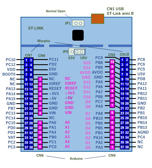
Below is a summary of the STM32F103RB pin numbers and their corresponding functions. Please note that these pin numbers are for the MCU itself and not for Nuleco's Morpho connector. For example, the first pin of CN7 is "PC10", which directly connects to pin 51 of the STM32F103RB.
From the pin definition table below, this pin can be used by default as 10 of the general-purpose I/O C port as input or output, but it can also be used with USART3_TX when remapped.
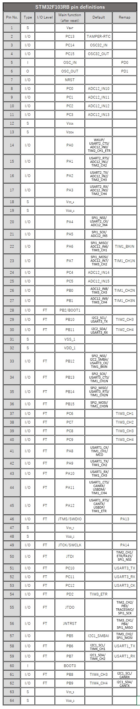
Pin type: I Input O Output I/O Input/output, S Supply power
I/O level: FT 5V withstand voltage Blank Supply voltage
Programming learning environment using the teaching material board
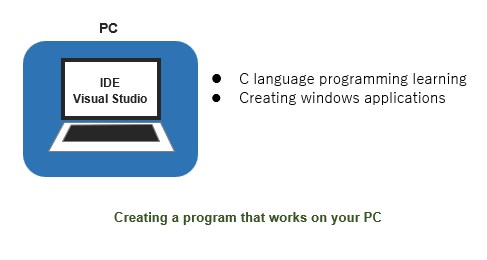
Usually, in order to learn C programming, you need to For example, a development environment such as Visual Studio is built as a development environment for the C language running on WINDOS to learn programming.
Because the program execution environment and the development environment are the same, the results of minor operations can be checked on the monitor display using the printf statement while learning.
This method is effective when the learning objective is clear, such as creating Windows applications, and it is possible to improve skills while learning. However, if the objective is simply to learn the C programming language, motivation may not be sustained unless there is a specific curriculum for learning programming.
The advantage of this method is that the C language can be learned using only a PC. However, the compiler is not designed for MCUs, so variable types and other specifications must be changed when applying this method to MCU C compiler.
In contrast, there is a way to learn C language using a teaching material board, which is introduced below.
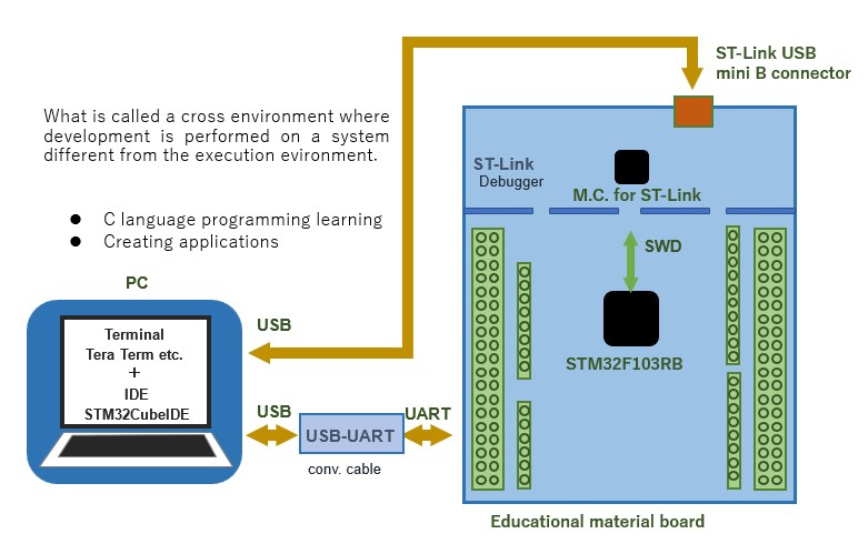
By configuring an environment that allows serial communication with a PC on the instructional board, a C language program running in the actual MCU can be monitored and displayed on a PC, enabling both practical C language programming and MCU operation to be studied at the same time. This is called a cross-environment, in which development is performed in a system (PC) different from the program execution environment (MCU).
In addition to a PC, a teaching board (MCU), a USB-UART conversion cable, and an ST-Link debugger are required to build the environment. This is a great advantage to be able to learn while checking. Another big advantage is that the C compiler is for the STM32 MCU, so what you have learned and become familiar with can be used directly in practice.
The combination of STM32CubeIDE, a comprehensive development environment for creating programs for the STM32 MCU, and the ST-Link debugger allows the program to communicate with the MCU and run the program. Serial communication is used to monitor and check the program operation on a PC.
Serial communication is performed on the PC using communication software called terminal software (terminal emulator). The connection to the MCU uses a UART-USB conversion cable, and the MCU power is supplied from the ST-Link connection, so for C language learning purposes, the MCU can be operated without an external power supply.
It is difficult for beginners to understand all the details of the environment construction, but the first step is to set up an environment that allows serial communication with a PC.
Minimum equipment required for learning microcontroller:
・Microcontroller board (with STM32F1xx Cortex-M3)
・USB cable(Mini USB Type-B)
・Debugger ST-LINK/V2 for program transfer :Nucleo board has built-in
・SWs for signal input (pushbutton SWs, etc.):Nucleo board has built-in
・Lamps for checking signal output (LED, etc.):Nucleo board has built-in
・Current limiting resistors and volume :For external LEDs, etc.
Tools that would be useful:
・USB-UART conversion cable (with this, input/output can be checked on PC monitor!)
Commercially available MCU board
Commercially available microcontroller boards with the STM32F1xx (Cortex-M3) series can be used to verify some of the contents of this site in practice.
However, the application program used on this site is for the specified educational material board (NUCLEO-F103RB), so it must be modified to match the specifications of the on-board MCU and clock.
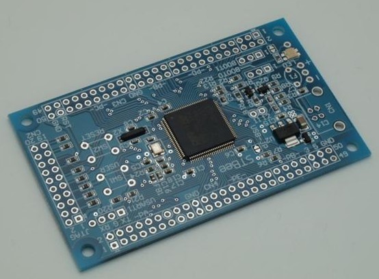
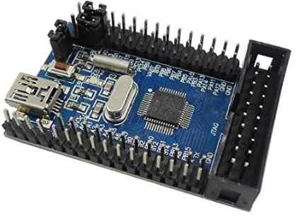
To select a commercially available teaching material board, the MCU must be of the STM32F1xx series and the pins PA13 and PA14 for the SWD debugger must be available.
Other parts for teaching materials
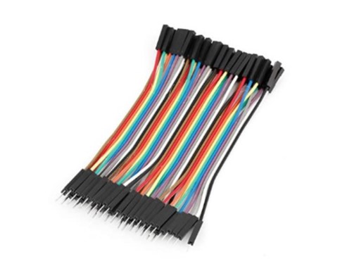
Solderless breadboards and jump wires are convenient for connecting the input/output components of an instructional board. Jumpwire connectors are basically male-to-male type for breadboards, but male-to-female and female-to-female types are also available.
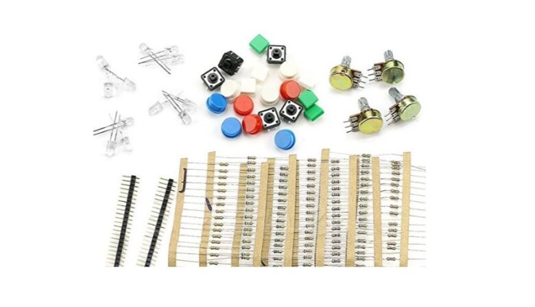
Pushbutton switches, LEDs, resistors, etc. are all that is needed as input/output parts, and recently some of these parts are sold together as an introductory kit for electronic construction. Resistors of about 330Ω and 1kΩ are used. Details are in the wiring diagrams used in each application in the "Application program samples used in practice" chapter.

Power supply
If you just want to check the program operation without using external components, an external power supply is not necessary because power is supplied from the ST-LINK debugger for program transfer. Normally, power from the PC's USB bus power can supply up to 300 mA, and the USB current is managed by a protection circuit on the ST-Link device side.
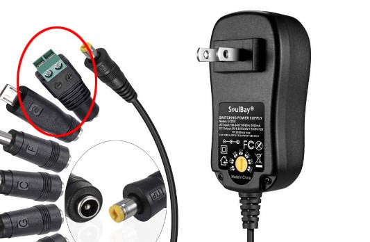
An external power supply (5/7-12 VDC) is required when installing input/output components with a load of more than 300 mA of power supply current.
For example, if the power supply from the USB port is insufficient for communication with the WiFi module, an external 5V power supply will stabilize the power supply.
In addition to USB bus power from the USB port, the Nucleo series boards can be powered by an external power supply. 5V external power (500mA max.) can be supplied to E5V (CN7-6), and 7~12V external power (800mA max.) can be supplied to the board. mA), connect to VIN (CN7-24 or CN6-8). When using an external power supply, set jumper pin JP5 on the board to the E5V side to enable it.
However, if jumper pin JP5 is set to the E5V side, the USB current protection circuit will be disconnected and will not function, which may damage the USB port of the PC in the worst case.
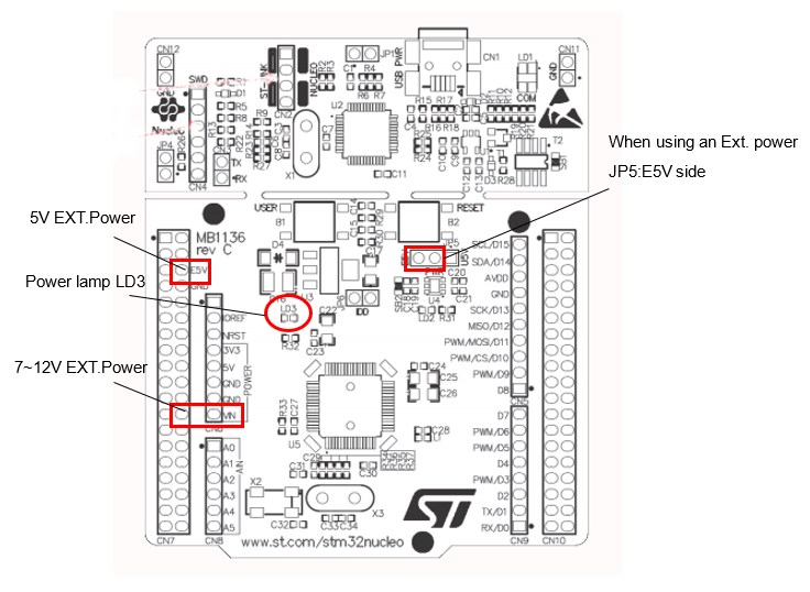
- Set JP5 to EV5 side
- Connect external power supply to E5V (5V) or VIN (7~12V)
- Check that power lamp LD3 is lit.
- Connect USB (it is important to connect the USB port last)
Three ways to supply power to the Nucleo board:
・Supplied from USB (JP5: U5V side) USB current management on ST-Link device side
・5V to E5V (JP5: E5V side)
・7~12V to VIN (JP5: E5V side)
(Important) When using an external power supply, turn on the external power supply first and connect the USB cable last!