Peripheral library for ARM STM32F1 series

Table of contents
MCU Peripherals

A peripheral library is a driver that allows you to easily set the control registers of peripheral functions (peripherals) in the specifications. From this point onward, we will provide specific explanations based on MCUs actually used on this site. Hereafter, peripheral functions will be referred to as peripherals.
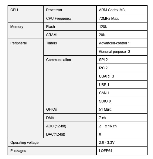
The model type of the target MCU is ARM Cortex-M3 STM32F103RB. The specification table of STM32F103RB is shown below. This MCU is a medium performance line model of the series.
The internals of the STM32F103RB are complex, but a simplified version is shown in the block diagram below.
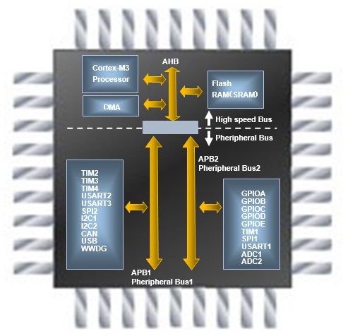
The CPU and memories are connected by the AHB (High Speed Transfer Bus), while peripherals are connected by the APB (Advanced Peripheral Bus). The APB (Advanced Peripheral Bus) is divided into APB1 and APB2, with low-speed peripherals connected to APB1 and high-speed peripherals connected to APB2.
Power consumption can be reduced by selecting and turning on only those functions that are used and turning off those functions that are not used.
The pin layout is shown in the figure below. As you can see, the lower left PA1 (15) pin represents the first GPIO port A, or GPIOA_1. The PA1 pin shares several functions besides general-purpose I/O. How to set them up will be explained in detail later.


ARM MCUs have low power consumption for their performance because unused portions can be turned off in detail.
Each peripheral can be individually turned on and off. This is not done automatically, but rather the function is selected at the time of programming.
The function of each peripheral is not turned on or off with a switch, but rather the function is set according to whether or not a clock is supplied. If the clock is not supplied, most peripherals (peripheral functions) will not operate.
SPL(Standard Peripheral Libraries)
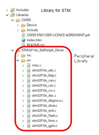
Libraries are stored in the integrated development environment as shown in the figure below. The "CMSIS" folder is a library for the ARM microcontroller core. Basically, you do not need to operate it.
In this folder tree, the files under the "STM32F10x_StdPeriph_Driver" folder are the Standard Peripheral Libraries (SPL) for each peripheral. The library contains several functions written in C language for each function setting. These functions operate the control registers, and the parameters given to the functions are the setting values of each peripheral of MCU.
The name STM32F10x_ means that this library is for the STM10x series microcontrollers; it cannot be used for MCUs with different specifications such as the STM32F4 series, so you must create a new project for each specification and use the corresponding library.
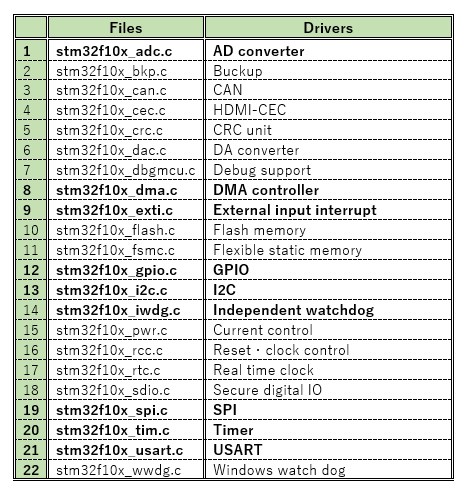
The following table lists the peripheral library files, with the most frequently used ones in bold. The main body of the peripheral library used is stm32f10x_xxxx.c and the header file stm32f10x_xxxx.h, in which functions are defined for each function setting.
In order to call the various functions of the peripheral library, stm32f10x.h must be included in the application program.
The peripheral library has many header files for each peripheral, but they are called from stm32f10x.h. Therefore, the entire functionality of the peripheral library can be used by simply including stm32f10x.h.
The header file stm32f10x.h itself is located under the "CMSIS" folder in "Device"-"ST"-"STM32F10x"-"Include".
For example, in the library, the GPIO header file is stm32f10x_gpio.h and the library body is stm32f10x_gpio.c.
Flowchart
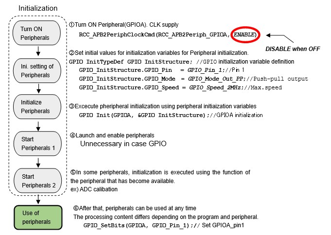
Here is a flowchart for enabling the peripherals with an example of setting Pin1 of GPIOA as a push-pull output. It is not necessary to understand the details of the configuration here, just get the flow.
Initially, the peripheral is OFF (no clock is supplied), so a clock is supplied to turn it ON (1). Next, set initial values to the initialization variables (2), and then execute initialization (3). Depending on the peripheral, a separate startup (4 and calibration (5) may be required.
Thus, the peripherals can be used arbitrarily in the application program after the initialization stage.
If the clock is supplied after initialization is set, the setting is not reflected.
The initialization variable of the peripheral is a structure variable of type GPIO_InitTypeDef in the case of GPIO, and the parameter is passed to the GPIO_Init function that executes the initialization (the part ②). It is defined in the header file stm32f10x_gpio.h.
Other peripherals are similarly defined in the library. Among peripherals, timers, for example, are highly functional, so initialization variables are structure variables divided into several groups for each function. There are also a wide variety of parameters to be set. Details are explained in each peripheral.
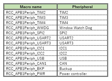
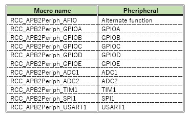
It was mentioned above that a clock is supplied to turn on a peripheral. Since the slow peripherals are connected to bus APB1 and the fast peripherals are connected to bus APB2, the clock supply for the peripherals is also provided by the target bus. The defined macro names of the peripherals connected to buses APB1 and APB2 are listed in the table below, respectively.
Each peripheral that belongs to APB1 executes the RCC_APB1PeriphClockCmd function and those that belong to APB2 execute the RCC_APB1PeriphClockCmd function to supply clock and set ON/OFF. "ENABLE" turns it ON and "DISABLE" turns it OFF.
Peripheral Library Summary
Many functions are assigned to the control registers of each peripheral. For example, for GPIOs, there is specification selection between input and output, and for inputs, there are four types of signal specification selection: analog, pull-up, pull-down, and digital voltage input, depending on the signal to be handled.
Since control registers are a type of memory, each register to be set has an address, which in the STM32 MCU is a 32-bit address; for example, the register to select the input/output specification for pin 1 of GPIOA is GPIOA_CRL with the address 0x40010800. The above specification functions are assigned to the register at this specific address, which is specified by a combination of 0 (OFF) and 1 (ON) digital values.
MCU is a digital system that functions by combining a number of switches, so specifications can be selected by writing 0s and 1s to the control register.
The peripheral library is a series of operations that are set in each control register are coded as a "macro" and blocked as a function, making it very convenient to use without being aware of register addresses and function details described in the reference manual.
The only knowledge required is how to use each peripheral library, so even beginners can easily start using MCU.
The next chapter explains the part actually done in the peripheral library. It is quite difficult to understand, but it will deepen your understanding of MCUs, so please try it when you get used to it.