System Clock[SysClk setting details for STM32]

The system clock is microcontroller-specific, so once it is set, it is not something that should be changed. However, a thorough understanding of the system clock will enable its application to other microcontrollers.
Table of contents
Clock of MCU

This chapter explains how to create the system clock, which is the operating frequency of MCU based on the clock signal generated by an oscillator such as a crystal resonator, and how to set the clock to be supplied to each peripheral.
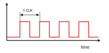
As explained in the chapter on "the basics of embedded technology", a clock is a pulse signal that serves as the timing for all circuits, including the CPU of MCU. The clock setting in an embedded device is important to ensure that MCU can operate at a speed that allows it to demonstrate its performance and consume as little power as possible.
It is important to be aware of what speed clock is being supplied when setting each peripheral. Although it may be a little difficult for beginners to MCU at first, it is not necessary to understand everything, but once you understand the mechanism and create a block function that summarizes the clock setting functions, all you need to do is change the parameters according to the application.
This section explains how to use the peripheral library for configuration, but since the clock configurations of MCUs are all similar, understanding the essential functions here will be applicable everywhere.
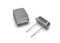
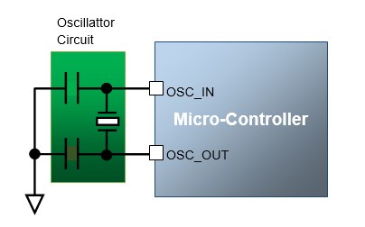
The STM32 MCU incorporates an RC oscillation circuit consisting of a resistor R and a capacitor C, in addition to an oscillation circuit using an external crystal or ceramic resonator to supply clock signals.
While the use of a built-in oscillation circuit has the advantage of simplifying the peripheral circuits of the microcontroller by eliminating the need for an external resonator, it is possible that the frequency may fluctuate due to variations among products and the surrounding environment.
On the other hand, an external oscillation source such as a crystal oscillator has a constant and accurate frequency; however, when connecting to external devices asynchronously, such as in UART communications, the clock must be accurate because an unstable clock may cause unstable communication speed and communication problems. See the section on "External Clock for MCU".
Whether the clock source is internal or external depends on the application use and is ultimately up to the designer.
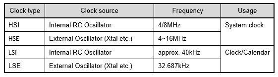
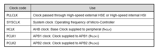
Clock source type
There are four types of clock sources available for STM MCU. This section explains how to generate the system clock from the HSE clock using an external oscillation source and how to set the clock to be supplied to each peripheral.
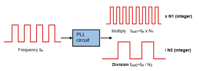
When an external oscillation source such as a crystal oscillator is used in the STM32 microcontroller or other microcontrollers, the oscillation frequency of the oscillator is not used as-is as the system clock (operating frequency), but is often made several times faster.
To achieve a high operating frequency, for example, it seems simple to use a 200 MHz external oscillation source to operate at a 200 MHz system clock, but the higher the frequency, the more power is consumed, the more heat is generated, and the more unstable the oscillation becomes.
Unlike PCs, embedded devices often have to endure use in environments with poor heat dissipation, so heat generation is fatal.
Therefore, an external oscillation source that is stable at a low frequency is used as the basis for a PLL circuit (phase-locked circuit) to increase the clock frequency by an integral multiple (multiplication) or divide it by an integer to make it smaller (division).
The above-mentioned PLL circuit always appears in the clock setting of MCU, but it is not so important to understand the principle when using MCU; it is enough to recognize that it changes the clock frequency.
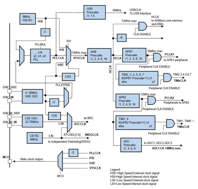
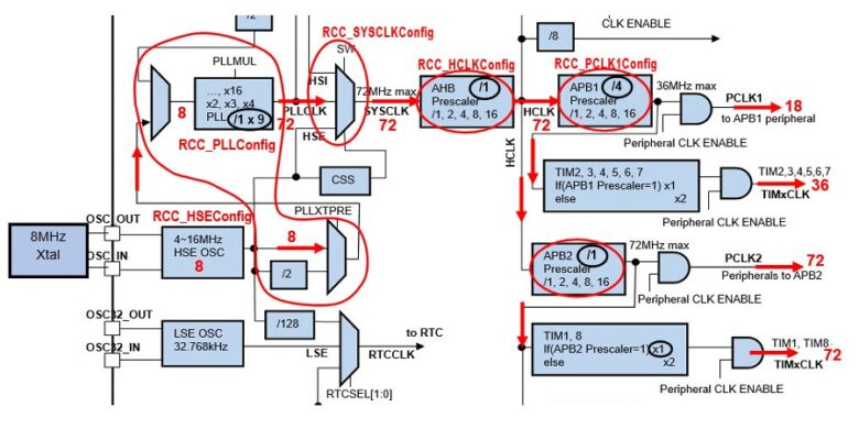
In the STM32 MCU, the clock is configured as shown in the figure above, and the system clock and peripheral clocks are created according to the parameters you set.
The clock settings may seem complicated at first glance, but once you understand how it works, you will be able to easily set it up outside of the peripheral libraries used here and in other microcontroller systems.
As a side note, when using the automatic code generation tool, the tool automatically creates clocks for the system clock and peripherals by simply entering the necessary parameters in a visually clear block diagram to create the clocks.
It is very useful, but even when using such a tool, you should first understand the function of the block diagram. This clock configuration is not limited to the STM32 MCU, but is used in all MCUs.
Clock Setting
We will now explain using the example of using an 8 MHz crystal for the external oscillation HSE. The clock setting procedure for the system clock SYSCLK at 72 MHz, the APB1 peripheral clock PCLK1 at 18 MHz, and the APB2 peripheral clock PCLK2 at 72 MHz is as follows.
① RCC System reset
First, reset the microcontroller clock system by executing RCC_DeInit().
Immediately after power-on, the clock system is in its initial state (Internal HSI: 8 MHz), so this function does not need to be executed, but it is executed for fail-safe reasons.
② Enable external clock HSE
Enables external clock HSE; the argument of the HSE enable function RCC_HSEConfig is RCC_HSE_ON to enable HSE and RCC_HSE_OFF to disable HSE.
For reference, there is also an argument RCC_HSE_Bypass, which is used to bypass the HSE by inputting an external clock source to the OSC_IN pin without using a crystal or ceramic resonator.
When using the internal clock HSI (8 MHz), execution of RCC_HSEConfig() is not necessary.
③ Standby for HSE readiness
Since the external oscillator is an oscillation circuit combined with a capacitor, it takes some time for the clock to stabilize after startup. To wait until it stabilizes, RCC_WaitForHSEStartUp() is executed to obtain the return value HSEStartUpStatus.
When the returned HSEStartUpStatus value is SUCCESS(1), the next process proceeds.
④ PLLCLK setting by PLL circuit
Set PLLCLK by PLL circuit.
The PLLCLK is created by executing RCC_PLLConfig.
Setting example: Division ratio 1, Multiplication factor 9
RCC_PLLConfig(RCC_PLLSource_HSE_Div1,RCC_PLLMul_9);
The first argument specifies the division ratio.
■ RCC_PLLSource_HSI_Div2 : Divides HSI in half and supplies to PLL
■ RCC_PLLSource_HSE_Div1 : Supply HSE to PLL
■ RCC_PLLSource_HSE_Div2 : Divides HSE in half and supplies to PLL
The second argument specifies the Multiplication factor to be specified for the PLL circuit.
■ RCC_PLLMul_x: 2 - 16 integers (set below the upper limit of MCU)
In the above program example, the HSE clock is 8 MHz with a division ratio of 1 and a multiplication factor of 9, so PLLCLK is 72 MHz.
⑤ Frequency divider setting for HCLK, PCLK1, and PCLK2
Next, divide settings for HCLK, PCLK1, and PCLK2 are made.
HCLK is generated by executing SYSCLK with the division ratio specified as an argument in RCC_HCLKConfig.
Argument divider ratio:
■ RCC_SYSCLK_Div1 : None
■ RCC_SYSCLK_Div2 : 1/2
■ RCC_SYSCLK_Div4 : 1/4
■ RCC_SYSCLK_Div8 : 1/8
■ RCC_SYSCLK_Div16 : 1/16
■ RCC_SYSCLK_Div64 : 1/64
■ RCC_SYSCLK_Div128 : 1/128
■ RCC_SYSCLK_Div256 : 1/256
■ RCC_SYSCLK_Div512 : 1/512
PCLK1 and PCLK2 are generated by executing HCLK with the division ratio specified as an argument in RCC_PLCK1Config() and RCC_PLCK2Config(), respectively.
Argument divider ratio:
■ RCC_HCLK_Div1 : None
■ RCC_HCLK_Div2 : 1/2
■ RCC_HCLK_Div4 : 1/4
■ RCC_HCLK_Div8 : 1/8
■ RCC_HCLK_Div16 : 1/16
⑥ Enable PLL circuit
PLL_PLLConfig() sets the PLL circuit multiplication factor, but the PLL circuit is not yet active.
RCC_PLLCmd() is used to start the PLL circuit. The argument ENABLE activates the PLL circuit, and DISABLE deactivates the circuit.
Setting example:
RCC_PLLCmd(ENABLE);
⑦ Select SYSCLK source
Since it takes some time for the PLL circuit to start properly after it is set to run, use RCC_GetFlagStatus() to check if the PLL circuit is ready, and if the return flag of this function goes from RESET to SET, it means it is ready.
The program waits while the return flag is RESET.
RCC_GetFlagStatus() can be used to check various states other than the PLL circuit.
Setting example:
RCC_GetFlagStatus(RCC_FLAG_PLLRDY);
The following is a description of the RCC_FLAG macro specified as an argument, which is related to clock settings. The setting example confirms that the PLL is ready.
Arguments (Flag Status):
■ RCC_FLAG_HSIRDY: HSI Ready
■ RCC_FLAG_HSERDY: HSE Ready
■ RCC_FLAG_PLLRDY: PLL Ready
■ RCC_FLAG_LSIRDY: LSI Ready
■ RCC_FLAG_LSERDY: LSE Ready
In addition, RCC_FLAG_PINRST, RCC_FLAG_PRTRST, RCC_FLAG_SFTRST, RCC_FLAG_IWDGRST, RCC_FLAG_WWDGRST, and RCC_FLAG_LPWRST are available for use as needed.
At the end of the clock setup, PLLCLK is specified as SYSCLK, the operating frequency of the system clock. This is set by executing RCC_SYSCLKConfig().
Arguments:
■ RCC_SYSCLKSource_HSI : Uses HSI not via PLL circuit
■ RCC_SYSCLKSource_HSE : Uses HSE not via PLL circuit
■ RCC_SYSCLKSource_PLLCLK : Uses PLL circuit
Setting example:
RCC_SYSLKConfig(RCC_SYSCLKSource_PLLCLK);
Finally, to check if PLLCLK is set to SYSCLK, the return value of RCC_GetSYSCLKCource() is checked and if it is as set, the operation is completed. In this program, PLLCLK is set, so if the return value is 0x08, the setting is complete.
return value:
■ 0x00 : HSI is used
■ 0x04 : HSE is used
■ 0x08 : PLLCLK is used
The program has been used as an example to explain the settings, but in reality, it would be sufficient to use the program as it is and change only the parameters. In reality, you can use this setup program as it is and change only the parameters.