External Clock for MCU [ARM Core STM32]
Of the clocks that are indispensable for using MCSs, this section explains external clocks. Although the crystal resonator in particular is a simple component, if the selection is not properly made, it can cause problems such as clock stoppage in the worst case. This section introduces practical tips for providing a stable external clock.
For details on the clock, please refer to System Clock "System Clock[SysClk setting details for STM32]"for an explanation.
Crystal resonator units are among the electronic components used in MCU peripherals, but like resistors and capacitors, they do not always function if attached. To ensure stable oscillation, capacitors with the optimal capacitance for the crystal unit are used, and compatibility (matching characteristics) with the MCU itself may be checked in some cases.
This is because a crystal resonator unit does not generate pulses by itself, but in combination with a capacitor creates a physical oscillation when a voltage is applied, so it is important to balance the capacitance parameters with those of the capacitor.
Table of contents
External clock with crystal resonator

Recent MCUs have a built-in RC oscillator circuit consisting of a resistor R and a capacitor C, so the system clock can be generated as an internal clock without the need to provide an oscillator outside MCU.
The STM32 MCU also has the advantage that it can be operated without an external oscillator if it is set to use the internal clock for the system clock. And the number of components can be reduced to realize space and cost savings.
However, since the frequency accuracy of the internal clock is inferior to that of the crystal resonator clock, and the frequency may vary depending on each product and the surrounding environment, such as temperature and operating voltage, it is necessary to make the right decision for each application.
For example, it is essential to set the baud rate with an accurate clock to synchronize asynchronous serial communication UARTs with other devices, so it is safe to use an external clock with high accuracy.
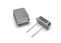
Crystal resonators are available in conventional metal packages and resin-molded packages. Although they oscillate much more stably than those of a century ago, care should be taken in applications with low supply voltage or with voltage fluctuations.
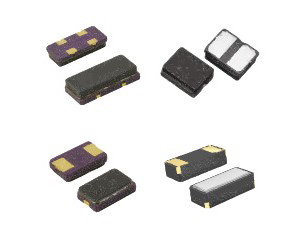
Standard crystal resonators in general metal packages are relatively stable due to their generous physical size. But sufficient verification may be necessary when using surface mount type (SMD) crystal resonators with small size.
The selection of an crystal resonator is not a matter of your own judgment alone; you may need to refer to similar examples of use, or you may need to check with the manufacturer because of compatibility with MCU. If you are not familiar with it, it is safe to adopt a type with a proven track record as it is.
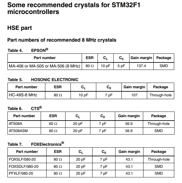
The optimum capacitance of the capacitor to be used in combination with the crystal is described in the o's data sheet or MCU's data sheet. Other components around the crystal resonator include a limiting resistor REXT, which may be used depending on the characteristics of the crystal .
To deal with incompatibility between the crystal and MCU in prototyping, a socket can be provided so that the crystal can be easily replaced with another type. This is only possible with the through-hole type.
Also, there are many theoretical analyses of crystal oscillation, but from the standpoint of MCU user, I think it is sufficient just to look through them.
When mounting a crystal resonator, there are precautions such as placing the PCB pattern as close as possible to MCU to minimize the effects of parasitic capacitance and inductance, so it is necessary to check with the manufacturer's specifications.
External clock with Ceramic resonator
In addition to crystal resonator, external clocks include what are called ceramic resonator. Like crystal resonator units, these clocks are based on mechanical resonance and are less affected by ambient temperatures, etc., and are slightly less accurate than crystal resonator units, but more accurate than internal clocks.
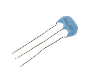
Clocks using ceramic resonators are intermediate between those using crystal resonators and those using internal oscillation circuits. They are inexpensive and can be comfortably selected by using a 3-terminal type that has a built-in capacitor required for the oscillation circuit.
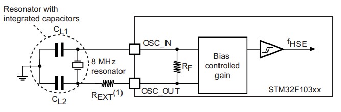
With the 3-terminal type, the area enclosed by the dotted line in the above figure can be replaced with a single component, which also saves space.
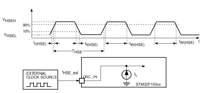
External clock with oscillator
Since crystal resonators and ceramic resonators are types that generate mechanical resonance when a voltage is applied, it is not impossible for the clock to stop if there is an error in parameter selection or if they are not compatible with MCU.
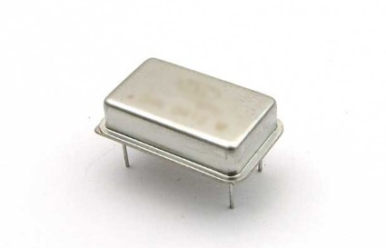
Therefore, instead of an resonator, an oscillator with a built-in oscillation circuit can be connected in place of the resonator. Although the unit cost of components is higher and the size is larger, this is a reliable way to generate pulses using only the power input. Simply connect the oscillator output to MCU's external clock input side (OSC_IN in the STM32 MCU).
■ When using crystal resonator units for the first time, it is safe to use a metal package (through-hole type) with a larger size.
■ If you are unsure, you may adopt as many examples of use as possible.
■ For prototyping, etc., it is possible to use a socket so that the resonator can be replaced with another type.
■ It is also possible to use a crystal oscillator instead of a crystal resonator, although the price will be a little higher.
External clock frequency setting
The STM32F1xx series firmware defaults to using an 8 MHz external clock. For this reason, many evaluation boards, including the Nucleo board, often use an 8 MHz crystal.
Exceptionally, the STBee board with STM32F103VE has a 12 MHz crystal, so the baud rate will not match that of other devices for serial communication, for example, unless it is reconfigured. So let's look at where to change the frequency of the external clock.
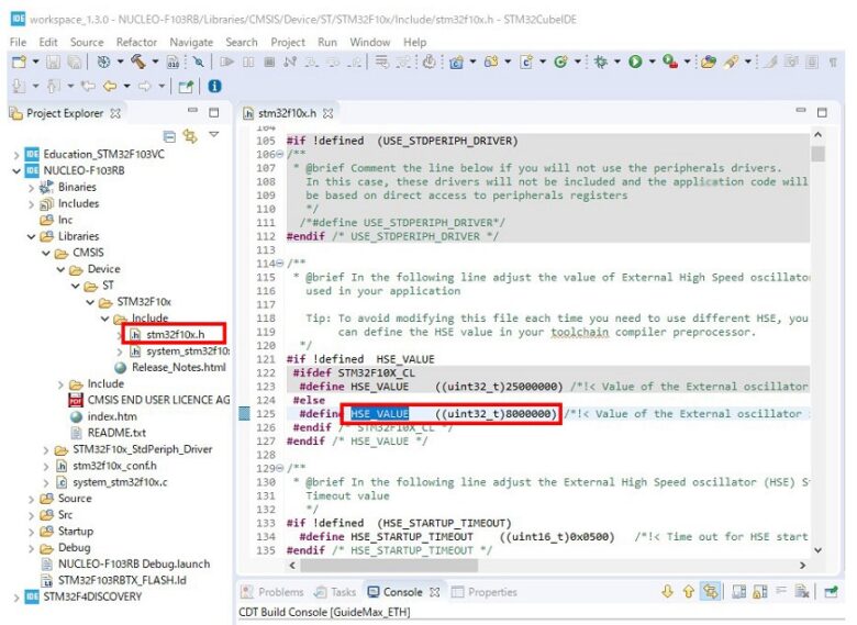
The external clock frequency is defined as HSE_VALUE in stm32f10x.h, so simply change this value from the default of 80000000 to the frequency to be used, e.g., 12000000 for 12 MHz.
In this issue, I have taken a look at external clocks.
For asynchronous UART communications that output high-precision pulses or are tuned to an external frequency, it is safe to use an external clock with stable accuracy instead of an internal clock. When handling a crystal resonator for the first time, you may be concerned about compatibility with MCU, but it is best to use one that is used on commercial boards as much as possible. It may be risky to use a small SMD type before getting used to it. When mass-producing corporate products, the manufacturer may be asked to conduct matching tests.