Embedded Hardware design [with Specific circuits]

Table of contents
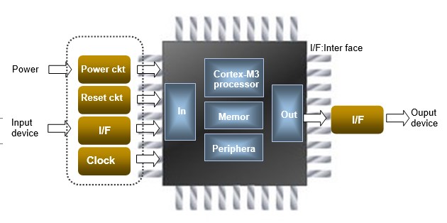
MCU and Peripheral Circuits

Since MCU is simply an IC by itself, it requires peripheral circuits composed of electronic circuits such as power circuits and interfaces between input/output devices and MCU for actual use. External clock and reset circuits are added as necessary. The peripheral circuits referred to here are circuits outside MCU.
Power circuit
The power supply for MCUs is generally 5 VDC or 3.3 VDC. Recently, many low-voltage applications are also available, and some can be operated with a single dry cell battery (1.2 V). Basically, a power supply circuit is required to obtain MCU operating voltage.
It is not necessary to design the entire power supply circuit itself, the operating voltage is obtained by combining AC-DC converters (switching power supply), DC-DC converters and LDOs (low dropout voltage regulators). The important thing in circuit design is to ensure that the power supply is designed for sufficient capacity.
If power is to be supplied to external devices that will be added later, the capacity must be secured even more firmly, or at worst the system will not boot.
When integrating into actual products, protection circuits around the power supply should also be provided to increase reliability. For this, refer to the specifications of each DC-DC converter or LDO.
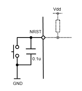
Reset circuit
The STM32 series MCUs have a power-on reset function, so a reset is automatically applied at each power-on without an external reset circuit. However, if the system freezes for some reason during operation, an external reset button switch can be added to enable resetting without turning the power back on.
Interface
Signals from input/output devices such as operation switches and sensors are usually not directly connected to the pins of the microcontroller, but are connected through a circuit called an interface.
The role of the interface is to convert the signal level of each device to that of MCU specifications and to prevent malfunction or damage to the device or MCU due to noise or sparks. The allowable current of each IO port of MCU is up to 8mA, so an interface is necessary except for applications that directly connect a small load.
There are so many specifications and types of interfaces that it is impossible to introduce all of them, but we will focus on the most basic and general-purpose Optocoupler isolation circuits.
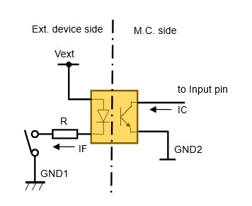
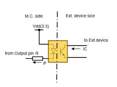
Both the input interface and output interface are isolated from MCU side and the external device side by a optocoupler. This prevents noise from entering MCU side and allows the external device side to use a power supply with specifications different from those of MCU side.
A optocoupler is an element that generally consists of a light emitting diode on the input side and a phototransistor on the output side.
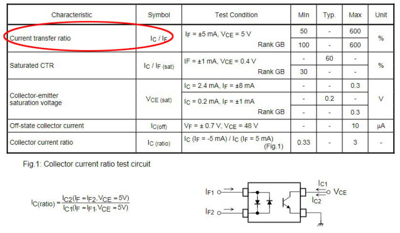
The ratio of the current IC at the output phototransistor side to the current IF flowing through the photodiode at the optocoupler input side is called the current transfer ratio (CTR = IC/IF x 100[%]). It is similar to the current amplification factor hFE of a transistor (bipolar type).
To ensure sufficient required current at the output side, IF on the input side is set by the input side resistance R, or adjusted by the output side supply voltage and load resistance RL. Since the conversion efficiency CTR varies and varies with operating conditions (temperature, aging, input current IF, etc.), a generous setting should be made.
For example, if the output device of MCU requires about 100mA (IC), and if the CTR is 50, setting the input resistance R so that IF is 5mA will theoretically allow up to 250mA (IC), so there is plenty of room. The larger the value, the higher the power consumption of MCU.
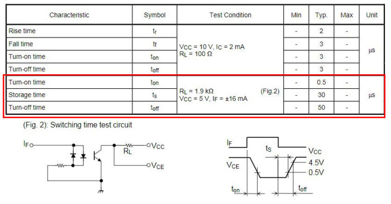
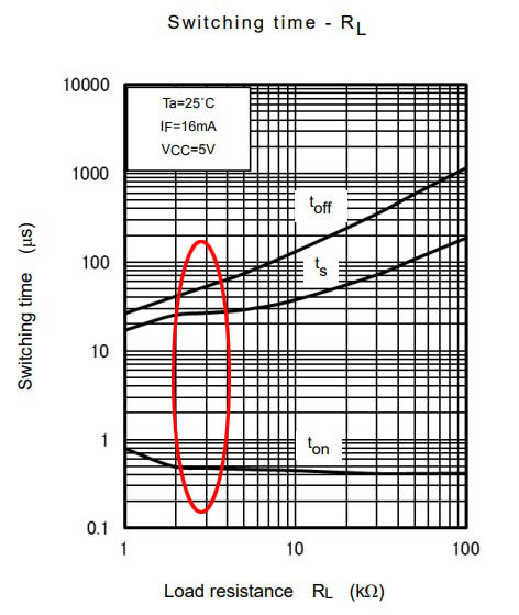
One characteristic of optocouplers that must be noted is responsiveness. This is sometimes called the switching characteristic. General-purpose photocouplers tend to have particularly long turn-off times, which become more pronounced when the output side load resistance is large. Use a high-speed type photocoupler when handling signals above several kHz.
RC filter
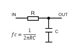
A filter is something that cuts or passes through components in a certain frequency range contained in a signal.
This section deals with low-pass filters, which pass through low-frequency components of a signal and cut off high-frequency components.
The RC filter is the simplest filter that can be constructed with the simplest circuit. Combining a resistor R and a capacitor C as shown in the figure makes a low-pass filter. fc is called the cutoff frequency and is the reference for the frequency to be cut. For example, if R is 100 kΩ and C is 0.1 uF, the cutoff frequency fc is approximately 16 Hz.
In the case of MCU with analog input or floating specifications and voltage signal input, inserting a low-pass filter can cut off high-frequency components including noise.
The ones configured in electronic circuits are called analog filters, while the ones configured as software in a program are called digital filters. Digital filters are more in depth, and I would like to introduce them when I have a chance.
Protection circuit with resistors
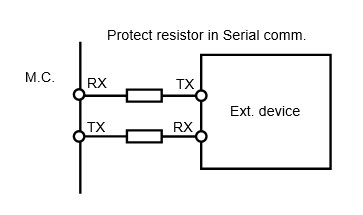
When directly connecting MCU to an external device, a protective resistor with a small resistance value (about 100Ω) can be inserted in series to prevent transient inrush currents.
When directly connecting MCU to an external device, a protective resistor with a small resistance value (about 100Ω) can be inserted in series to prevent transient inrush currents.
Protection circuit with diodes
A diode is an element called a rectifier. It has anode (anode) and cathode (cathode) polarity, and current flows only in one direction, from anode to cathode. This characteristic of only allowing current to flow in one direction is often used in protection circuits.
Circuits often seen in MCU peripheral circuits include reverse connection protection and overvoltage protection.
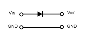
Reverse Connection Protection:
Reverse connection protection is achieved by inserting a diode in series with one of the power supply lines, so that the normal connection is in the forward voltage direction and power is supplied. Strictly speaking, the supply voltage is reduced by the voltage drop across the diode.
Surge Protection:
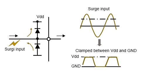
MCUs and other ICs are vulnerable to overvoltages called surge voltages, so circuits consisting of diodes are often used as protection circuits. MCUs have built-in protection circuits on each pin.
Even if a large signal exceeding the power supply is input, it is returned to the power supply side by the diode and is not transmitted to the input side. As a result, the signal is clamped (limited) by the supply voltage and is called a clamp circuit.
Clock Circuit
The need for a clock signal as a reference signal to operate MCU was explained in the section on system clock. Since recent MCUs usually have a built-in RC oscillation circuit as an internal clock, they can be operated without an external oscillation circuit.
Depending on the application, an internal RC oscillation circuit can be used and no external oscillation circuit can be used to reduce design effort and cost.
When matching the same operating frequency as the other party, as in asynchronous serial communication, accuracy is required, so it is necessary to use an external oscillation circuit.
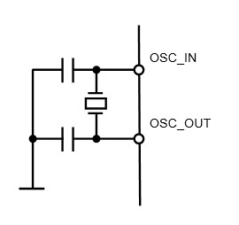
A crystal or ceramic resonator is used as an external oscillation circuit in combination with a specified capacitor.
Crystal oscillators are also subject to compatibility (matching) when used in combination with microcontrollers, so consideration should be given when using crystal oscillators for the first time.