General Purpose I/O GPIO[usage details of STM32]

In this section I explains in detail how to use the general-purpose input/output GPIOs of the STM32 MCU. To be able to use GPIO, the most basic and frequently used of the peripherals, requires not only programming but also an understanding of the electronic circuits that make up the interface, and therefore, an understanding of the key points of the STM32 MCU operation. See the section on "Basic hardware circuits around Microcontroller".
Table of contents
What are General Purpose Input/Output GPIOs?

General Purpose Input/Output, also called GPIO (Genaral Purpose Input/Output), is a port (pin) whose input/output can be arbitrarily controlled by software. Signals input to the pins are taken into the CPU as information, and signals are output from the CPU in MCU to the pins.
The GPIO circuit configuration of the STM32 MCU is shown below; the STM32 MCU can use the peripheral library to make the specified pin specification an input or an output.
For inputs, the circuitry in the input driver section is used to specify four types of inputs: pull-up, pull-down, floating, and analog inputs, depending on the function used.
When a pull-up or pull-down input is specified, the specified pull-up or pull-down resistor turns ON, respectively, and the information is passed to the input data register through the Schmitt trigger circuit. The Schmitt trigger circuit shapes the waveform of the input digital signal.
When a digital voltage signal is used as input, specify a floating input. In this case,the pull-up and pull-down resistors are turned off.
When an analog signal is used as input, the signal is sent directly to the AD converter circuit without going through the Schmitt circuit.
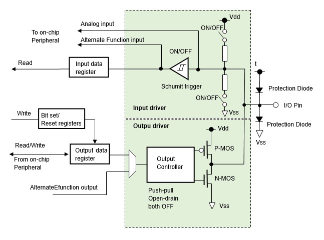
For outputs, four types of outputs are specified according to the function used: push-pull for general-purpose outputs, open-drain, push-pull and open drain for alternate function outputs.
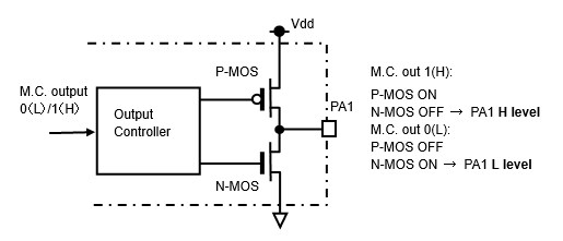
When a general-purpose push-pull output is specified, the output pin outputs a H-level voltage when the output is ON and a L-level voltage when the output is OFF.
When an open drain output is specified, only the N-MOS of the output circuit functions. When the output is turned on, the N-MOS is turned off, so the output pin is in a floating indefinite state that is neither a H-level voltage nor a L-level voltage. When the output is turned off, the N-MOS is turned on, so the output pin is a low level voltage.
If the port to be specified is not a general-purpose port but an output of a peripheral function, specify the output of the alternate function. Again, two types, push-pull and open-drain, are specified according to the peripheral.
How to use GPIO peripherals
Now let's explain how to actually set up the GPIO peripheral library by utilizing the GPIO peripheral library, which can be found in the following figure.
Set port A pin1 as push-pull output
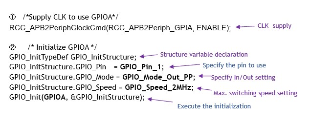
① Clock supply to GPIOA
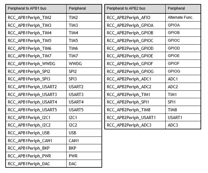
First, supply a clock to the GPIO to be used. Check and select whether the peripheral is connected to the APB1 or APB2 bus.
The first argument of the clock supply function RCC_APBxPeriphClockCmd() specifies the peripheral to be connected to the APBx bus.
The second argument is ENABLE to start supplying and DISABLE to stop supplying.
Arguments are configuration parameters used in the function. In the case of the GPIO A port, it is connected to the APB2 bus, so the RCC_APB2PeriphClockCmd function is specified to supply the clock and turn on the function.
Setting Example:
RCC_APB2PeriphClockCmd(RCC_APB2Periph_GPIA, ENABLE);
The macros to the clock supply functions in the table below are defined in stm32f10x_rcc.h.
② Initialization of GPIOA
Next, initialize GPIOA (using the GPIO_Init function).
In the case of GPIO, macro functions to set the control registers are described in stm32f10x_gpio.c. The variables and structures used in these functions are described in stm32f10x_gpio.h. The variables and structures used in these functions are defined in stm32f10x_gpio.h.
GPIOA is initialized using the GPIO_Init().
Setting Example: GPIO_Init(GPIA, &GPIO_InitStructure);
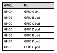
The first argument of the function specifies the GPIO port to be set. The available ports are limited depending on MCU.
The second argument, GPIO_InitStructure, is a structure variable that groups configuration parameters and is defined in the header file stm32f10x_gpio.h. Before using it, declare GPIO_InitTypeDef GPIO_InitStructure;.
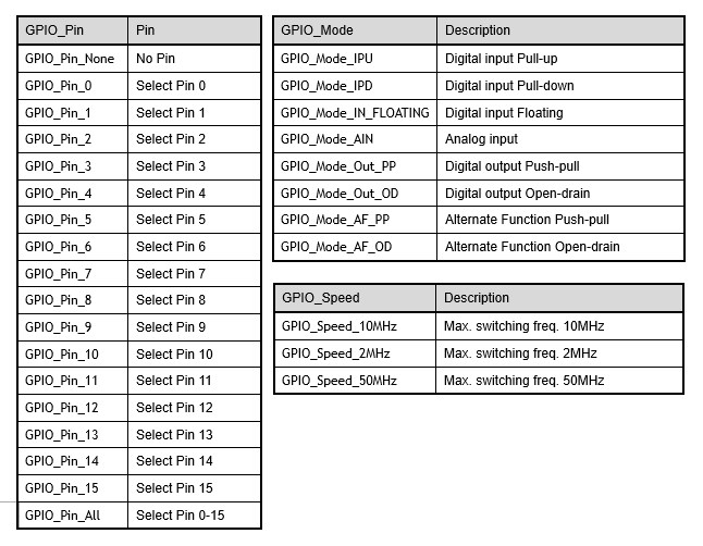
The GPIO_InitStructure structure variable contains the configuration parameters in the function as members, specifying the pins to be used, input/output specifications, and in the case of output, the maximum switching speed. The parameter details are shown in the table below.
There is an alternate function for the output, which is when the pin is not just a GPIO input/output, but also an output for a peripheral function such as a timer or UART. The output specifications that should be specified for each peripheral are described in each peripheral.
Setting Example: GPIOA_1 Push-pull output max. switching freq.2MHz
GPIO_InitTypeDef GPIO_InitStructure;
GPIO_InitStructure.GPIO_Pin = GPIO_Pin_1;//(0x0001)
GPIO_InitStructure.GPIO_Mode = GPIO_Mode_Out_PP;//(0x10)
GPIO_InitStructure.GPIO_Speed = GPIO_Speed_2MHz;// (0x02)
After specifying the configuration parameters, execute the initialization function GPIO_Init(). Specify the target port for each port (A to G ports). Thereafter, the initialized ports can be used arbitrarily in the program.
Alternate function and remap of GPIOs
Alternate function
Although we have so far proceeded on the assumption that MCU's ports are used with GPIOs, the initialization process is also necessary when the ports are used with peripherals (peripheral functions) other than GPIOs.
In the STM32, which ports can be used for which peripheral functions is predefined; the function that allows each STM32 port to be used for input/output for applications other than GPIO is called the alternate function.
External interrupts using the port are also included in the alternate function. When using the port as an output for peripherals in the alternate function, set GPIO_Mode_AF_PP (alternate function push-pull) or GPIO_Mode_AF_OD (alternate function open drain) in the I/O specification item.
When using the alternate function, the clock must be supplied to turn on the alternate function.
Setting Example: When using the alternate function
RCC_APB2PeriphClockCmd(RCC_APB2Periph_AFIO, ENABLE);
Remapping
Remapping is used to utilize a different function than the alternate function originally assigned to the STM32 as default. The following is an explanation of when this function is used.
If MCU has a relatively single function, remapping may not be necessary because the standard default alternate functions are sufficient, even if GPIOs or peripherals are used for ports.
As systems become more complex and multifunctional, multiple peripherals (timers, UART communication, etc.) are used simultaneously in a single MCU. Since the number of pins in MCU is limited, the more functions are added, the more difficult it becomes to use them simultaneously as desired.
In such cases, the remap function allows you to remap (reallocate) the necessary functions you MCU want to use to other pins, so you can utilize MCUr's functions more efficiently. However, it is important to check the pin definition table in the specification sheet carefully because the number of pins that can be remapped is limited depending on MCU.
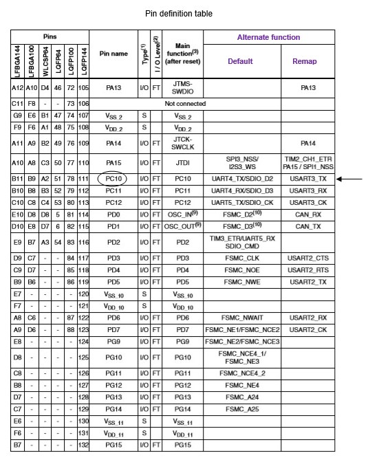
Looking at port PC10 in the pin definition table, the alternate function is assigned to UART4_TX or SDIO_D2 by default. Therefore, when a clock is supplied to either UART4 or SDIO peripheral to be used, the peripheral on the supplied side turns on and functions.
In other words, as it is, only UART4 or SDIO can be used. But this pin is assigned UART3_Tx for remapping. After remapping, UART3_TX can be used on this pin.
Remapping is required, for example, in the following cases.
I want to use UART3 for serial communication, but the pins near PB10 of default UART3 as an alternate function are already used for other purposes
So, I looked for a pin that can be used for UART3 in the remap and found that it is assigned near PC10. If a pin near this area is available, UART3 can be used by setting the remap function.
The remapping is set up according to the procedure shown in the figure below.
The following is an example of remapping to assign TX and RX of peripheral UART3 to PC10 and PC11, respectively.
① GPIO structure variable declaration
GPIO structure variable declarations need only be executed once, so we will start at the beginning.
② Clock supply to GPIOC
Clock is supplied to port C to use ports PC10 and PC11.
③ Clock supply to Alternate function
Supply a clock to the alternate function to use the peripheral UART3 and the remap function.
④ Setting PC10 as UART3_TX
PC10's UART3_TX is a push-pull output type, but it is a peripheral output, so set it to an alternate push-pull output. The switching speed should be set faster than the set communication speed (baud rate). After setting, execute the GPIO_Init function to initialize it as an alternate push-pull output.
⑤ Setting PC11 as UART3_RX
Set UART3_RX on PC11 to floating digital voltage input. After setting, execute the GPIO_Init function to initialize it as a floating input.
⑥ Remap execution
After initializing each pin, perform a remap.
Remapping is performed by executing the GPIO_PinRemapConfig function. The first argument of the function specifies the peripheral to be remapped. As mentioned above, remapping can not be performed at any point, but is assigned in advance.
There are two types of remapping: partial remapping, in which only part of the function is remapped, and full remapping, in which all of the function is remapped.
Setting Example:
/* partial remapping */
GPIO_PinRemapConfig (GPIO_PartialRemap_USART3, ENABLE);
⑦ GPIO resetting
Executing the remap function may include unused ports in the alternate function. In the above configuration example, only two ports of UART3, PC10 (UART3_TX) and PC11 (UART3_RX), are to be used after remapping.
If you want to use PC12 included in the alternate function by the remap function as a GPIO or the default alternate function (UART5_TX), simply set it to become the original function. In the above example, PC12 is reconfigured as a general-purpose input.
These are the steps to execute the remap function. The remap function is an effective function that allows more efficient use of microcontroller functions with a limited number of pins. When designing a system with a certain amount of multiple functions, the remap function is very useful because it allows you to configure pin assignments flexibly.
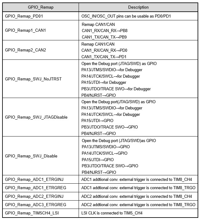
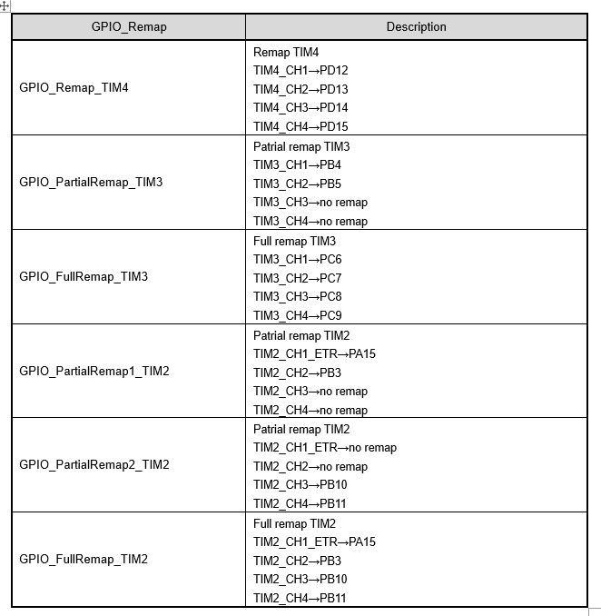
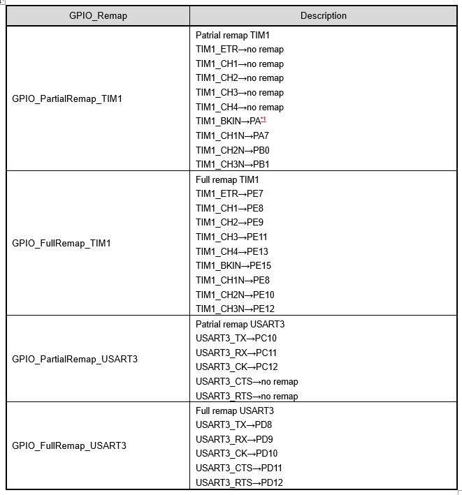
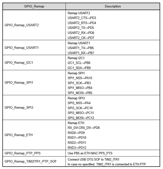
The allocation of the remapping function is summarized in the corresponding table, which should be set while checking it together with the pin definition table in the specifications.