About pulses used in MCUs [essential in control systems]
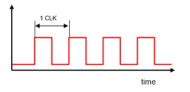
Table of contents
Hardware and Pulse

Pulse is a technology closely related to hardware circuits. Embedded engineers who work with control systems have many opportunities to handle pulse signals in particular, so it is important to understand how transistors and other hardware circuits generate pulses.
Pulse is a technology that is closely related to hardware circuits. Because embedded engineers who deal with control systems have many opportunities to handle pulse signals in particular, it is important to understand how transistors and other hardware circuits generate pulses.
It can be said that the free use of pulses is to some extent a given in control system programs. Signals used in communication are also pulses in a broad sense. However, since a dedicated circuit creates everything according to the format, you do not need to be aware of the pulses themselves.
Pulse type
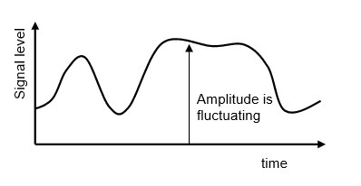
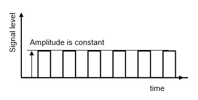
Pulses are a type of digital signal and are indicated by the microcontroller as an ON/OFF state relative to an analog signal.
Analog signals continuously fluctuate in signal level amplitude over time, while the amplitude of digital signals is always constant.
In MCU, a basic pulse called a clock is given by a pulse oscillator such as a crystal oscillator and serves as a timing signal for each process. The clock is an important reference signal for MCU, which, like the beating of the heart, will stop functioning if it stops.
One cycle is one clock, for example, at a clock frequency of 1 MHz, one cycle is 1 us, so 1,000,000 pulses are generated per second.
A signal without voltage, i.e., just a switch turning on and off as an electric circuit, is called a potential-free signal, while a signal with voltage is called a voltage signal.
The concept of pulses is very important for understanding the input/output of MCU, which is a digital system, as well as its internal processing.
In the circuits we have dealt with so far, for example, in input circuits, pull-up and pull-down resistors are used to convert no-voltage signals into voltage-containing pulse signals, while in output circuits, push-pull outputs provide voltage-containing pulse signals and open-drain outputs provide potential-free pulse signals.
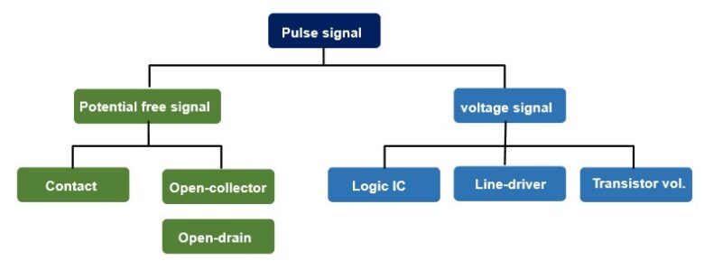
Potential-free signals are contact signals from operating switches, relays, etc., or signals output with an open collector using a transistor or an open drain using a MOSFET, and are called dry contacts when the signal source is a contact. When the signal source is a contact, it is called a dry contact. To use it as a pulse signal, a voltage is applied to the signal circuit and a current is applied to the load, which becomes an electrical pulse signal.
The transistor open collector type is often used for sensor outputs, control equipment signal outputs, etc. Sink outputs with NPN transistors are common in Japan, while specially in Europe, many products have source outputs with PNP transistors.
The characteristic feature of potential-free signals is that the power supply can be freely selected on the side that receives the signal (input side). In other words, a separate power supply from the output side can be used. In this case, ground can be separated, which is also effective for noise suppression.
When using a potential-free signal as the input to MCU, it is necessary to connect an additional external pull-up or pull-down resistor as described earlier to provide tMCU with a 1 (High) or 0 (Low) voltage signal. Some MCUs have built-in pull-up and pull-down resistors.
A voltage signal is, as the name implies, a voltage pulse. Pulses generated by a circuit assembled with a logic IC are voltage signals.
Voltage levels are fixed, and two typical types are TTL and CMOS, which are used according to specifications. The TTL standard refers to logic circuits composed of bipolar transistors, but often simply refers to a 5 V signal voltage.
TTL Standard
■ TTL general 1 (High)/0 (Low) level
VIH(min. voltage to be regarded as High)approx. 2.0V
VIL(max. voltage to be regarded as Low)approx. 0.8V
i.e., the logic is 1 (High) at 2.0V or higher and 0 (Low) at 0.8V or lower.
CMOS Standard
■ CMOS general 1 (High)/0 (Low) level
VIH(min. voltage as High)0.5-0.7 x Vdd (if Vdd=3.3, 1.65-2.3V )
VIL(max. voltage as Low)0.2 x Vdd (if Vdd=3.3, 0.66V )
Note that the 1 (High)/0 (Low) level threshold changes depending on the supply voltage Vdd.
The current MCU voltage, Vdd, is 3.3V, but lower voltages, 1.8V and 0.9V, are also available. It is necessary to understand and use the MCUs well because there is a risk of breakdown if the voltage level exceeds the specification voltage level.
Line drivers are balanced signals (differential signals) used to avoid the effects of transmission noise and output logic signals of opposite polarity. Although a balanced input circuit is required on the signal input side, it is characterized by stable operation over relatively long distances. Line driver pulses are not directly used in the input/output of MCU, but can be used in a dedicated line driver IC.
Of the voltaged signals, voltaged pulses with transistor elements as switches are often used in MCUs. As mentioned above, an open collector type potential-free signal is converted to a voltage pulse with a pull-up or pull-down resistor.
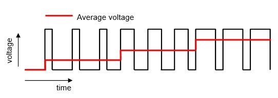
Pulse Width Modulation:PWM
Pulse width modulation lengthens or shortens the pulse width (the period during which the pulse is on or off: duty ratio), effectively adjusting the average value.
For example, the speed of a DC motor can be controlled in proportion to the voltage by adjusting the motor power supply voltage. The simplest way to change the voltage is to connect a variable resistor in series with the load and change the resistance value.
In this method, the motor current can be changed by changing the variable resistor, but a large loss (=I2R) is generated by the resistor R and the current I.
In contrast, the pulse width modulation method called PWM does not change the voltage value (amplitude) according to the resistance value, but adjusts the average value by adjusting the period during which the voltage is ON and OFF with constant amplitude i.e., the pulse width. Therefore, the loss is smaller than that of voltage control by resistor R.
The desired output voltage is obtained by switching, or turning on or off, the input voltage by means of a power electronics circuit called a switching circuit. The Frequency-converter we often hear about is an application of PWM.
Semiconductor devices used in switching circuits include Thyristors, GTOs, Power transistors, MOSFETs, and IGBTs.Recently, SiC(silicon carbide) and GaN (gallium nitride) have emerged as next-generation devices, replacing conventional silicon-based devices.