Bits, bytes, words and digital logic [essential for Microcontroller]

In MCU programming, bit operations are often used in addition to the four arithmetic operations on data. The concepts of bits, bytes, and words are indispensable, especially when MCU skills improve and MCU registers are set directly. This chapter provides a basic explanation of digital logic, so please make sure you understand it well.
Table of contents
Bits, bytes, words

A bit is a unit of data quantity that distinguishes between two states (0 and 1). 1-bit data can be expressed as 0 and 1 to distinguish between OFF and ON states.
Inside MCU, numerical values are handled in binary numbers, and the number of digits in binary numbers is called the number of bits.
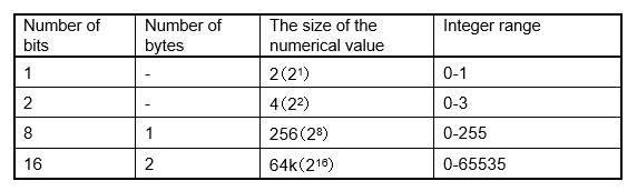
- When the number of bits is 1, it is called 1-bit, and only two ways digits(21) of numbers, 0 or 1, can be handled.
- When the number of bits is 2, it is called 2-bit, and can be handled in 4 ways digits(22) from 00 to 11 in binary and from 0 to 3 in decimal.
- When the number of bits is 8, it is called 8-bit, and can be handled in 256 ways digits (28) from 0000000000 to 1111111111 in binary and from 0 to 255 in decimal.
- When the number of bits is 16, it is called 16-bit, and can be handled in 65536 ways digits (216) , from 0 to 65535 in decimal.
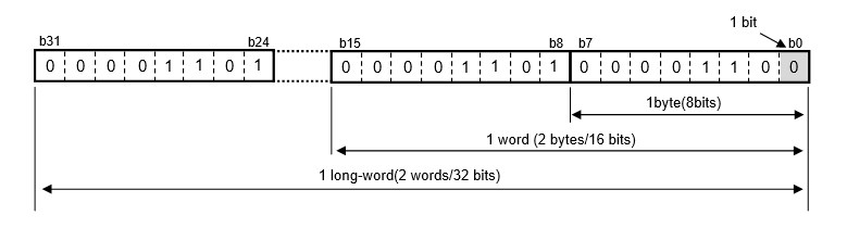
One byte is 8 bits. Similarly, 16 bits are called a word and 32 bits are called a longword.
A byte is represented as B, so for example, 16 kbytes is represented as 16 kB.
Digital logic
The concept of digital logic is essential in programming as well, and I will not explain the software aspects here, but only the basics that you need to understand at a minimum.
Among AND (AND: logical conjunction), OR (OR: logical OR), NOT (NOT: negation), NAND (NAND), NOR (NOOR:), and XOR (XOR: exclusive OR), in particular, please understand the truth table of AND and OR, operations and NOT.
What I would like to discuss here is the digital logic used in MCU peripheral circuits. Since MCUs are digital circuits, electrical signals are either Vdd, the power supply voltage level (in general notation for digital circuits), or Vss, the ground level (in general notation for digital circuits). In digital logic, a signal level of Vdd is said to be 1 or "H" level (High), while a signal level of Vss is 0 or "L" level (Low).
In actually constructing the circuit, AND corresponds to a series connection and OR corresponds to a parallel connection.
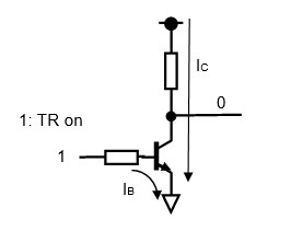
In addition, when designing an interface for an output circuit, it is necessary to know whether the voltage level of the actual output should be 1 or 0 when outputting digital 1 to a microcontroller. In this case, NOT is used to invert the logic. In a circuit, a NOT is used to invert the logic by using a single switch element such as a transistor.
When MCU output is 1, IB flows to the base of the transistor, which is the switch element, and the transistor turns ON.
When the transistor is turned on, the collector current IC flows through the transistor, and the resulting output is almost 0 V (strictly speaking, the output is not 0 because of the voltage drop Vce), which is inverted from MCU output.
The function of transistors is explained in detail in "Basic hardware circuits around Microcontroller".
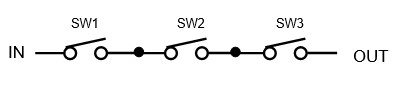
Let's look at an AND, OR, NOT circuit composed of switches.
If the switches are defined as 1 when ON and 0 when OFF, the input of the AND circuit is connected to the switches in series, so when all switches SW1, SW2, and SW3 are ON, the output OUT is 1, that is, ON.
In the OR circuit, the switches are connected in parallel, so if any of SW1, SW2, or SW3 is ON.
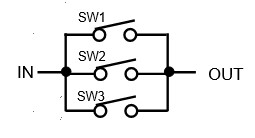
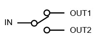
A NOT circuit is a NOT circuit because when the input is 1, OUT1 is 1 but OUT2 is 0 and the output is an inverted output. Inserting NOT is also called inverting logic.
The idea of logic is an important concept to understand as it is used not only within the program but also around the circuit.