Timer/Counter[STM32 Timers Details]

Table of contents
Timer counters on MCUs have a wide range of applications, such as counting the number of input pulses given externally, calculating input pulse frequency, outputting arbitrary frequency pulses, outputting PWM pulses, and measuring time with timer counter combinations other than pulses.
The timer/counter peripheral of the STM32 has so many functions that it is difficult to understand them all. This site explains the basic operation of the timer/counter and the various outputs using the timer.
The library uses SPL, but it will not be difficult to port it to HAL or other systems in the future if the basic video is understood.
Peripheral timer/counter

Among the peripherals (peripheral functions) of microcontrollers, timer counters are probably the most frequently used.
The timer/counter function is indispensable for embedded technology because the program itself consists of a combination of processing time and elapsed time concepts. If you can master this function, you will be able to develop a wide range of applications, so be sure to understand it well.
The SysTick timer, the system timer described in the previous chapter, was a relatively simple one that counts the system clock, which is the operating frequency, and generates periodic interrupts, which are processed within it. However, since the CPU executes the interrupt processing, the higher the speed, the greater the burden on the CPU.
In contrast, peripheral high-performance, general-purpose timers operate outputs directly by a dedicated circuit independent of the CPU, thus reducing the burden on the CPU and improving efficiency compared to system timers, which require interrupt processing.
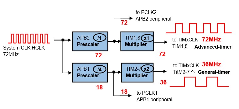
The Advanced-control timers TIM1 and TIM8 (depending on the microcontroller) are connected to the APB2 bus and clocked through the APB2 prescaler and multiplier circuit (here 72 MHz clock). General-purpose timer TIM2-7 (depending on the microcontroller) is connected to the APB1 bus and is supplied with a clock through the APB1 prescaler and multiplier circuit (in this case, a 36 MHz clock).
The Advanced-control, general-purpose timers described in the following section are capable of generating interrupts at regular intervals, like a system timer, as well as generating arbitrary-frequency pulses and interrupts.
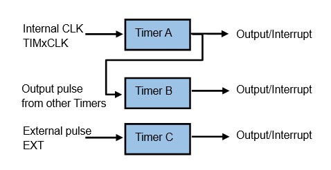
It can count not only the internal clock supplied to the timer, but also signals from external sources and output signals from other timers.
When the external clock source of the STM32 MCU timer is used as the clock source, there are two clock input modes: external clock mode 1, in which the pins of each channel for the timer (TIMx-CHy: x timer number, y channel number) are used for clock input, and external trigger only pin (TIMx-ETR) for the timer is used for clock input. External clock mode 2 is available.
Advanced-control timer and General-purpose timer
Here, I mention the difference between Advanced-control timer and General-purpose timer in the STM32 MCU. Both already have sufficient functionality, but the Advanced-control timer has the usual timer functions plus functions to generate PWM with dead time and complementary outputs, etc. The general-purpose timer has the same functionality as the ordinary timer, but it has a different functionality.
This function is a highly specialized function required to control the switching timing of power electronics such as inverters used for motor control, so it is not needed in normal applications.
In addition, when using Advanced-control timer, it is safe to set all functions even if they are not used because the timer output may be disabled if settings that are not necessary for general-purpose timers are not made.
Since general-purpose timers are multifunctional enough, )I recommend using a general-purpose timer (TIM2-7: depends on the microcontroller) with simplified settings until you become accustomed to using it.
Note: For the STM32F103RB with NUCLEO-F103RB, timers are selected by TIM1-4.
Only TIM1 is Advanced-control timer.
Timer/Counter Operation
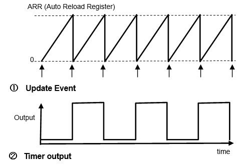
A register that stores the count of input clock pulses is called a counter register, and a register that sets the upper count limit is called Auto Reload Register (ARR).
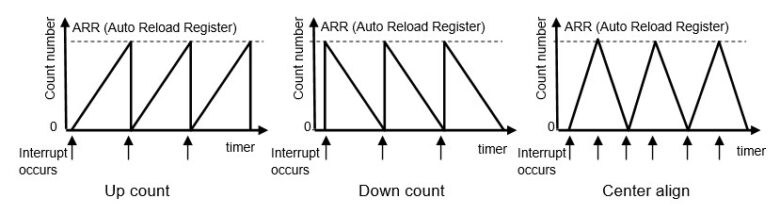
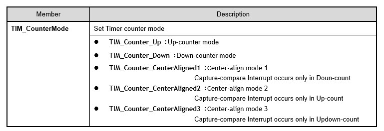
There are three pulse counting methods: up-counting is the method of adding pulses from count 0 to the setpoint ARR, down-counting is the method of subtracting pulses from the setpoint ARR to 0, and center-aligned counting is the method of repeatedly adding and subtracting pulses between 0 and the setpoint ARR.
In the case of up-counting, the counter overflows when the count (counter register value) reaches the ARR and the next count is made, causing an interrupt, etc. In the case of a down-counting, when the count reaches 0 and the next count is made, the counter underflows and generates an interrupt, etc. In the case of a center-aligned counting, the counter overflows when the count reaches ARR by addition, and underflows when the count reaches 0 by subtraction, causing an interrupt or other interrupt to be generated.
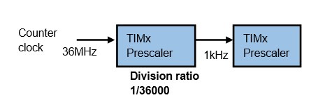
Each timer has a built-in frequency divider called a prescaler. The prescaler consists of a 16-bit counter, so the counter clock can be arbitrarily slowed down to a maximum of 1/65535 (1/216).
If overflow during addition or underflow during subtraction occurs during a counting operation, an update event such as an interrupt is generated. The general-purpose timer repeats the update event. In the Advanced-control timer, it is possible to set the timing of the update event and the number of times the counter repeats, but this is not mentioned here.
The role of the timer function is to
(1) Generate events such as interrupts in response to count results
(2) Change the state of timer output according to the count result
(3) Measurement of external clock frequency counts and pulse widths
(1) is used in the same way as the SisTick timer in the previous chapter.
(2) generates a pulse output using a counter and is used, for example, as a speed input command value in motor control.
(3) is the use of a combination of (1) and (2) to measure the time interval of a signal.
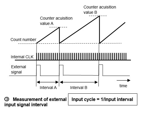
For example, if you want to measure the input interval of an external signal, you can simply use a timer.
Counts the internal clock for measurement fine enough for external signals. When an external signal is input, the current count is first acquired (count acquisition values A and B) and then reset as a count start signal. Then, it repeats counting the internal clock for measurement until the next external signal input.
The number of counts is the time interval between external pulses (input intervals A and B), i.e., the external pulse speed (reciprocal of the time interval) is measured. As described below, more accurate measurement can be made if the external signal is an interrupt input.
How to use Advanced-control/General-purpose timer peripheral
The first step in learning the functions of a timer is to actually use it, but let's start with the basics to understand how to use it. To begin with, we will explain the basic output compare mode programmatically.
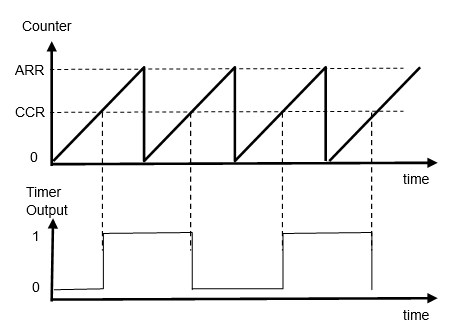
Output compare mode is a mode in which the counts are compared with the capture compare register (CCR: Capture Compare Register) set between 0 and the Auto Reload Register (ARR: Auto Reload Register). The output changes when the count number matches the CCR.
The following is an explanation of the settings in the actual program.
Example of output compare mode setting
Purpose:To output 5 kHz pulses in Output compare mode of a general-purpose timer
■ Timer uses only CH4 (PA3) of TIM5 output channels CH1-4
■ Clock supplied to timer is 36MHz
■ Counter operation is up-counter mode and output comparison mode
Note: For STM32F103RB with NUCLEO-F103RB, timers are selected by TIM1-4
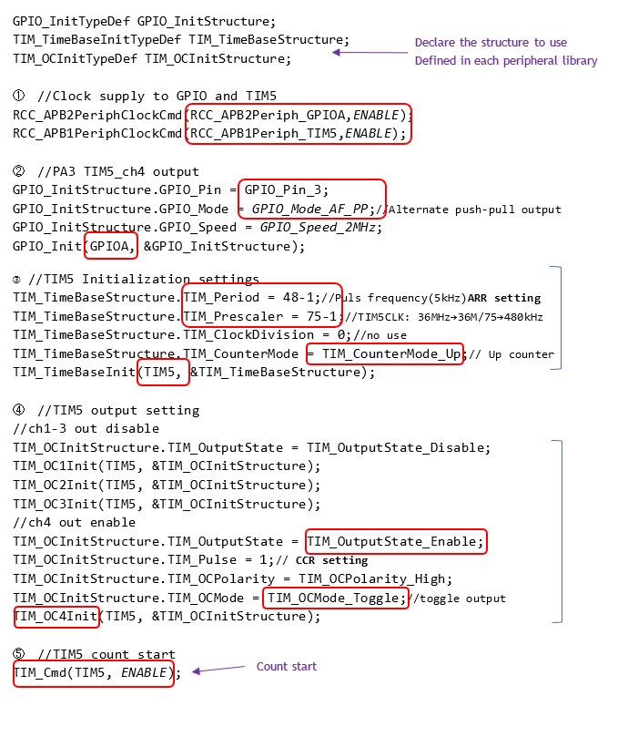
① Clock supply to GPIO and timer TIM5
GPIO port A is connected to APB2 and TIM5 is connected to APB1 to supply clock to each peripheral. In the case of high-performance timers (TIM1 and TIM8: depends on MCU), they are supplied to APB2.
② GPIO settings used for timers
Set the output port GPIO of the timer to be used. set the timer output alternate output to PA3.
③ Timer initialization
Next, the timer is initialized (TIM_TimeBaseInit function). Since there are a wide variety of initialization items, let us explain them one by one.
Timer initialization setting (3) specifies the timer prescale and counter operation mode. The initialization TIM_TimeBaseInit() is used.
Example of timer initialization function execution:
TIM_TimeBaseInit(TIM5, &TIM_TimeBaseStructure);
The first argument of the function specifies the timer to be set, TIM5, etc. The second argument is a structure member, as shown below.
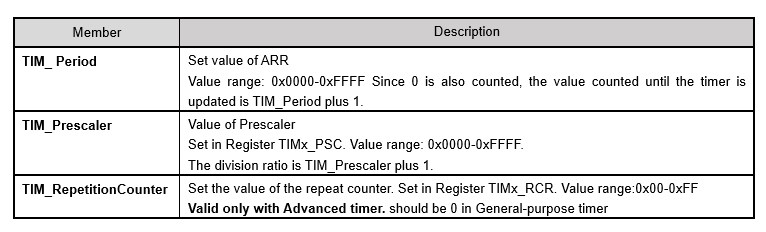
In the configuration example, TIM_Prescaler is set to 74(75-1) to divide the 36 MHz clock by 75 to supply 480 kHz (TIM5CLK) to TIM5.
To generate a 5 kHz timer output, the output should be inverted (toggled) every 10 kHz, so 47(48-1).

In this example, the up-counter mode is set.

④ Timer output settings
Set the timer output TIM_OCxInit(). In this example, only CH4 is enabled.
Detailed setting of output comparison mode (4) specifies the timer output specification parameters
Example of output comparison mode initialization function execution:
TIM_OC4Init(TIM5, &TIM_OCInitStructure);
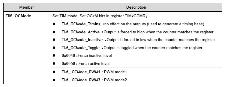
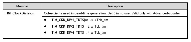
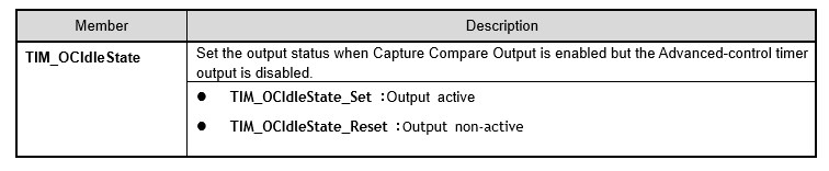
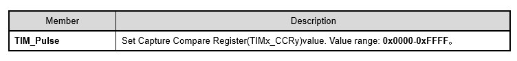
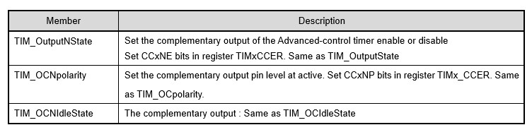
The second argument of TIM_OCxInit() is a member of TIM_OCInitTypeDef type structure, which is summarized in the table below. The following is an example of a general-purpose timer.
⑤ Timer starts counting
After all settings are completed, the timer starts counting TIM_Cmd().
Output occurs from this point on.
Now that the timer has been set, execute TIM_Cmd() to activate the timer and start counting.
Execution example of TIM_Cmd: TIM_Cmd(TIM5, ENABLE);
The second argument of TIM_ Cmd () is ENBLE to start counting and DISABLE to stop counting.
At this point, a 5 kHz push-pull output begins on PA3 connected to CH4 of TIM5.
In this program example, only one output is provided by CH4, but if other channels CH1-CH3 are used simultaneously and separate CCR (capture compare register values) are specified for each channel, the same pulse with a different phase can be output.
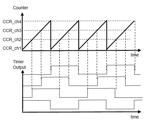
To shift the phase at arbitrary timing
If you want to shift the phase of CH4 at arbitrary timing The phase of CH4 can be changed with the TIM_SetCompare4 function.
Execution example of TIM_SetCompare: TIM_SetCompare4(TIM5, CCR_VALUE);
The first argument of the function specifies the timer to be set, TIM5, etc. The second argument specifies the value of CRR corresponding to TIM_Pulse, a member of the output comparison mode setting.
To change to any frequency
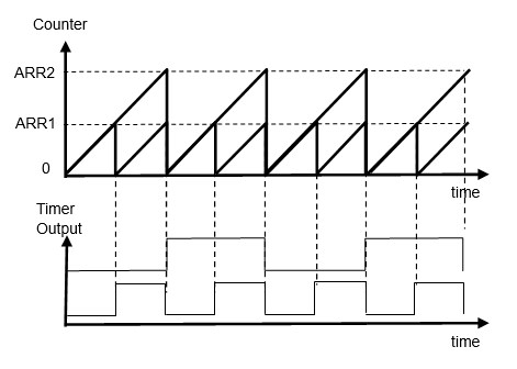
If you want to change the frequency of TIM5, you can use TIM_SetAutoreload() to change the frequency.
Excution example of TIM_SetAutoreload: TIM_SetAutoreload(TIM5, ARR_VALUE);
The first argument of the function specifies the timer to be set, TIM5, etc. The second argument specifies the ARR value corresponding to TIM_Period, a member of the timer initialization function. The figure shows an example using an up counter, but it is better to use a down counter because the ARR is changed during counting.
Only for Advanced-control timer output
For general-purpose timers, this completes the setting, but to enable the outputs of the Advanced-control timers, add TIM_CtrlPWMOutputs (TIMx, ENABLE).
Timer Applications
So far, timers have been used to change the count cycle (frequency) by changing the value of the automatic reload register (ARR) and the output timing (phase) by changing the value of the capture compare register (CCR).
Other uses of the timer include PWM output and counting an external high-speed clock signal, some of which we would like to introduce.
PWM mode output
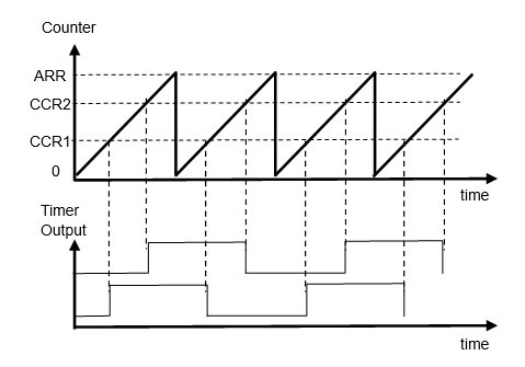
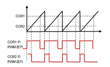
When up-counting, PWM mode 1 is High when the count is less than CCR and Low when it is not.

During up-counting, PWM mode 1 is High when the count is less than CCR and Low otherwise. PWM mode 2 is its inverted output.
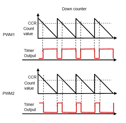
The characteristic of PWM output is that the output period (cycle count) is constant and the ON/OFF ratio (duty ratio) can be changed by changing CCR.
The setup is almost the same as in output compare mode, just specify TIM_OCMode as TIM_OCMode_PWM1 or TIM_OCMode_PWM2 among the members of the second argument of the TIM_OCxInit function. Note that the output will be twice the frequency when TIM_OCMode_Toggle is specified for TIM_OCMode in output compare mode.
External high-speed clock counting
Let us introduce the application of timers to count external high-speed clocks.
External Clock Mode
The STM32 timer has the ability to measure external pulses. Encoders are often used as sensors to detect the position and speed of actuators such as robots, etc. To count external pulses, the timer is used as an external clock mode. To use the external clock mode, execute TIM_TIxExternalClockConfig() immediately after initializing the timer (executing the TimeBaseInit function).
Excution example of External clock mode function:
TIM_TIxExternalClockConfig(TIM3, TIM_TIxExternalCLKSource_TI1, TIM_ICPolarity_Rising, 0xf);
The first argument of the function specifies the timer to be set, TIM3.
The second argument specifies the input clock pulse target.
■ TIM_TIxExternalCLK1Source_TI1, which reads the edge of TI1, the pin input of CH1
■ TIM_TIxExternalCLK1Source_TI2, which reads the edge of TI2, the pin input of CH2
■ TIM_TIxExternalCLK1Source_TI1ED reading both TI1 and TI2 edges
The third argument specifies the edge to be detected by TI1/TI2 from the following
■ TIM_ICPolarity_Rising with rising edge detection (polarity intact)
■ TIM_ICPolarity_Falling with falling edge detection (polarity reversed)
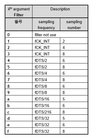
The fourth argument specifies the type of filter shown below. This is to prevent chattering and other noises when reading high-speed encoder pulses. If you are not reading particularly fast pulses, it is probably a good idea to specify the highest sampling value "f". I think it is better to adjust the value by actually operating the device.
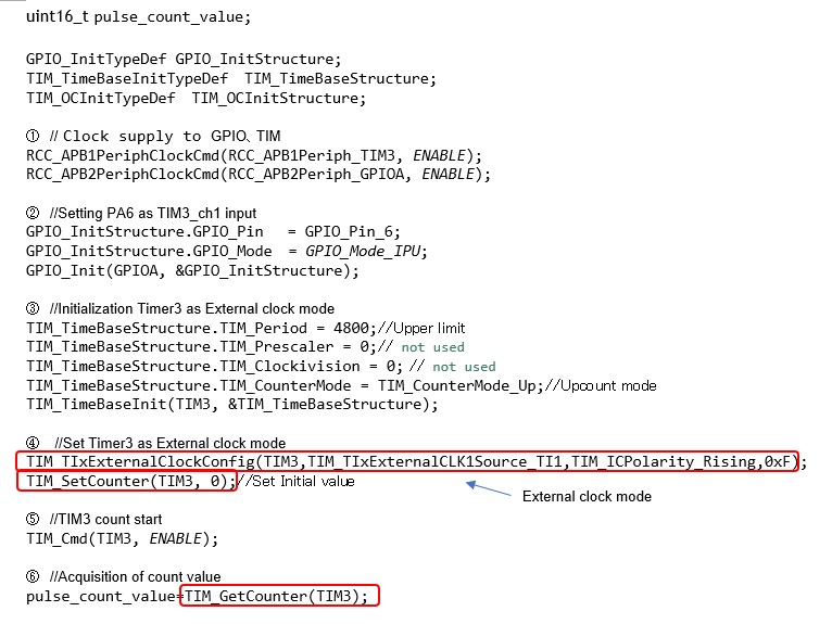
① Clock supply to GPIO and TIM4
In the example using CH1 (PA6) of TIM3, GPIO port A is connected to APB2 and TIM3 is connected to APB1, so the clock is supplied to each peripheral.
② GPIO initialization
Set according to the specifications of the external input. In this example, pull-up input is used to use pulses from the no-voltage contact input.
③ TIM initialization
It may be possible to omit initialization of TIM3 for external clock counts, but it should be performed.
④⑤ Set TIM to external clock mode and start counting
Execute the TIM_TIxExternalClockConfig to use TIM3 in External clock mode.
The filter should be set to "f" if it is not a problem, since the larger the sampling frequency, the duller and more noise sensitive it will be.
⑥ Get Count value
Input pulses are acquired at any timing in the application program.
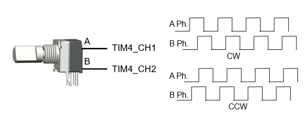
Encoder interface mode
The STM32 timer can count high-speed pulses, such as those from an incremental encoder input as an external signal, using only the timer function. In this case, the timer is used as the Encoder interface mode. To use the encoder interface mode, execute TIM_EncoderInterfaceConfig() immediately after the timer initialization (execution of the TimeBaseInit function) to set the mode.
Excution example of the function:
TIM_EncoderInterfaceConfig(TIM4,TIM_EncoderMode_TI1,TIM_ICPolarity_Falling,TIM_ICPolarity_Rising);
The first argument of the function specifies the timer to be set, TIM4 etc..
The second argument specifies that
■ TIM_EncoderMode_TI1, which reads the edge of TI1, the pin input of CH1
■ TIM_EncoderMode_TI2, which reads the edge of TI2, the pin input of CH2
■ TIM_EncoderMode_TI12 reading both TI1 and TI2 edges
The third argument specifies the edge to be detected by TI1 from the following
■ TIM_ICPolarity_Rising with rising edge detection (polarity intact)
■ TIM_ICPolarity_Falling with falling edge detection (polarity reversed)
The fourth argument selects the edge polarity when TI2 detects an edge, in the same way as TI1.
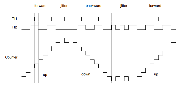
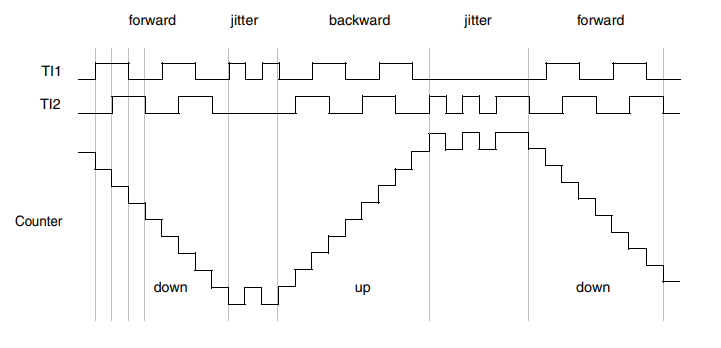
In encoder interface mode, the following patterns are used for counting.
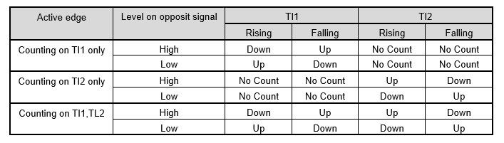
Specifying the edge polarity as inverted inverts the counting direction.
In the Encoder interface mode, the pulse edges of the encoder are counted, so the resolution is 2x for the edge counter of TI1 or TI2 only, and 4x for the edge counter of TI1 and TI2.
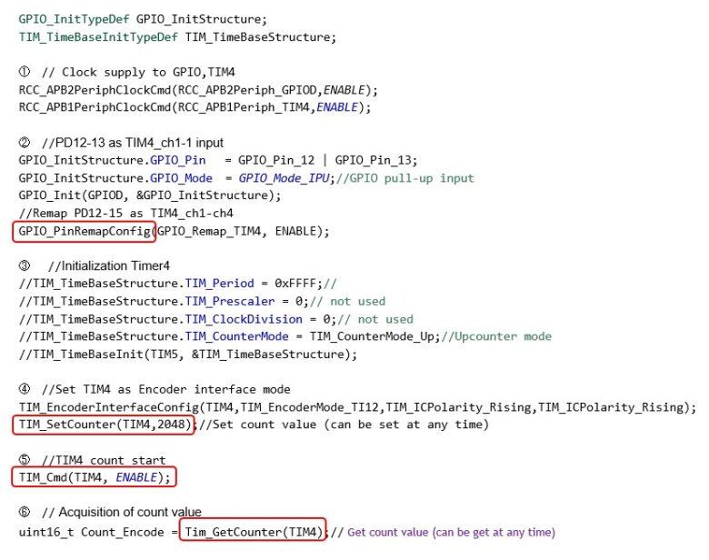
① Clock supply to GPIO and TIM4
GPIO port D is connected to APB2 and TIM4 is connected to APB1 to supply clock to each peripheral.
② Remap execution after GPIO initialization
Perform remapping after GPIO initialization if necessary
③ TIM4 Initialization
It may seem that the initialization of TIM4 can be omitted for external clock counts, but it should be performed.
④ Set TIM4 to encoder face mode
Execute the TIM_EncoderInterfaceConfig() to use TIM4 in Encoder interface mode.
In the mode that detects both TI1 and TI2 edges, the pulse resolution is quadrupled because the number of counts is doubled. In either mode, up-counting and down-counting are switched according to the phase of TI1 and TI2.
⑤ TIM4 count starts
Finally, TIM_Cmd() is executed to start counting.
⑥ Get Count value
The counter value of TIM4 is obtained at any timing in the program.