Heart rate monitor using pulse sensor and STM32 Nucleo

Try an application that counts the pulse, which is a slow pulse, and displays the heart rate per minute.
Table of contents
Creating a pulse rate sensor using a photo reflector and operational amplifier

This section provides an explanation of an application that counts pulses and displays heart rate. The application to realize the heart rate application includes a good balance of elements necessary for learning, such as knowledge of analog electronic circuits, GPIO of the STM32 MCU, interrupts and serial communication.
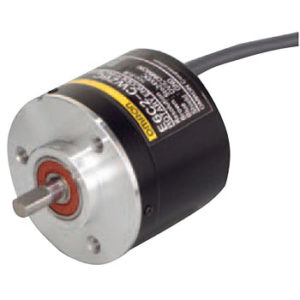
The sensor that detects the pulse uses a component called a photo reflector, which is commonly used in electronic construction.
This photo reflector consists of an LED that emits infrared light and a transistor that detects the reflected light. In electronic construction, it is also used for line tracing, which uses the difference in the amount of light reflected by different colors to determine the presence or absence of black lines.
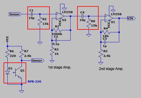
When the fingertip is placed against the photo reflector, changes in the hemoglobin concentration of the capillaries in the fingertip can be detected as changes in reflectance, but these changes are so minute that they are difficult to count even if they are input directly as electrical signals into MCU. Then,the pulse is amplified to a stable pulse using a component called an operational amplifier. There are various types of amplification circuits, and the one I use is just one example, but there is ample information available on the Internet, so it is a good idea to try various types.
Although a single-stage operational amplifier may work, two stages are used here. Since we want to take only the changes in the photo reflector signal as pulses, an RC high-pass filter (cutoff frequency: approx. 1 kHz) is used at the entrance to cut off the DC component by combining a capacitor C and a resistor R.
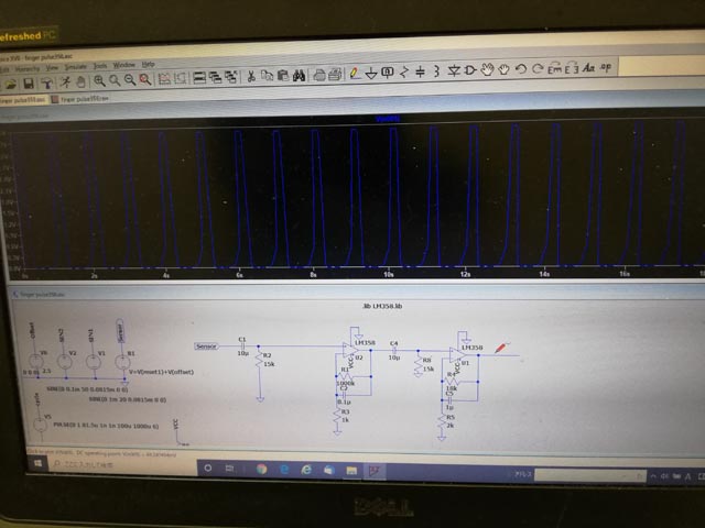
Let us examine the characteristics of the above circuit using a circuit simulation called LTSpice®. The input signal is a square wave with an amplitude of 1mV, an offset of 2.5V, and a period of 1s. Since a reasonable waveform appears at the output, we will configure the circuit with this waveform.
Circuit simulation is a powerful tool that can be used in place of prototyping, as it allows the user to confirm rough component selection, resistor values, capacitor capacitance, and other parameters before creating the actual circuit.
Although it would be easier and more reliable to use a completed pulse rate sensor as a product, here I have decided to use a photoreflector as a learning device to realize a heart rate monitor while also performing electronic construction.
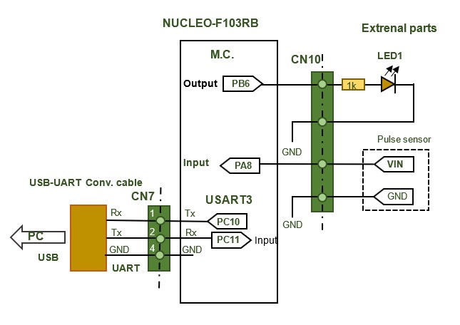
Connect pulse sensor signal and LED for output monitoring to MCU
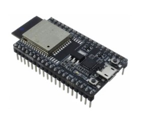
Since VIN at the output of the operational amplifier is directly connected to MCU as an input, the power supply of the operational amplifier is common to MCU power supply so that the maximum input voltage does not exceed MCU power supply voltage. (Some STM32s can accept a 5V input depending on the pin, but not all; check the STM32F103RB specification sheet for details.)
Program Description
The pulse sensor signal amplified by the operational amplifier is input to PA8 as a voltage pulse signal. Set PB6 to a general-purpose push-pull output to light an LED synchronized with the input pulse as a heart rate monitor.
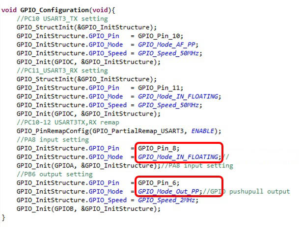
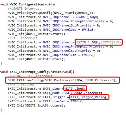
PA8 is set to interrupt for use as an external interrupt signal. The interrupt input is conditioned on the rising edge of the pulse.
Interrupt settings are explained in detail in "Various interrupts [Interrupt details in STM32]".
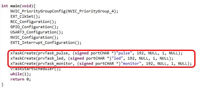
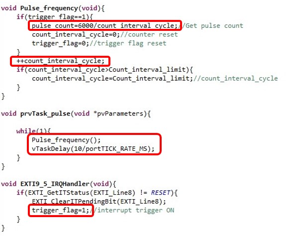
Use RTOS to categorize tasks by role. The tasks are prvTask_pulse (executed every 10 ms) for measuring the pulse pulse interval, prvTask_led (executed every 100 ms) for turning on the LED, and prvTask_monitor (executed every 1000 ms) for sending the calculated heart rate to the PC.
How to use real-time OS (FreeRTOS) tasks is explained in detail in "FreeRTOS task management basics [For Learning and Practice: Specific Usage]".
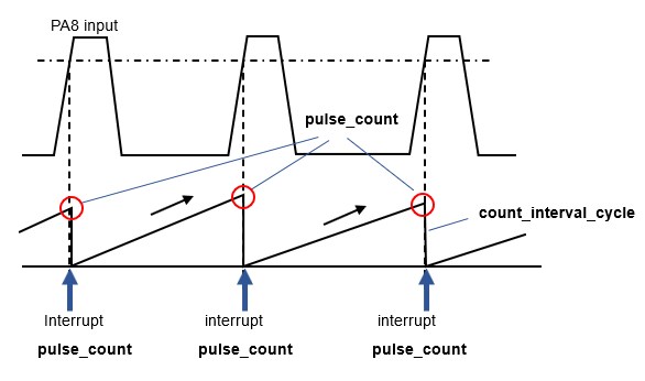
The following is a time chart of pulse pulse counting: An interrupt is generated at the rising edge of the PA8 interrupt input pulse, and the interrupt handler EXTI9_5_IRQHandler is called. Here, the flag triger_flag=1 is used to indicate that an interrupt has occurred.
When prvTask_pulse, a task for measuring the pulse pulse interval running every 10 ms, receives an interrupt notification with trigger_flag=1, it adds counts (count_interval_cycle) every 10 ms (10 ms clock counts). The heart rate (pulse_count) is calculated. After processing the calculation, the flag trigger_flag for interrupt notification and the count_interval_cycle are reset. The heart rate should be the number of interrupt inputs per minute, and in the case of the count_interval_cycle clock count value every 10 ms, it is 6000 divided by the count_interval_cycle.
Pulse sensor input
When you place your fingertip on the photo reflector of the pulse sensor detection section in the circuit actually configured, you can see that the pulse is detected and the signal is moderately amplified by the operational amplifier. You can see that the results of the simulation and the actual circuit are similar.
In the measurement program, the analog signal from the pulse rate sensor is counted as a pulse input with an interrupt.
LED and monitor outputs
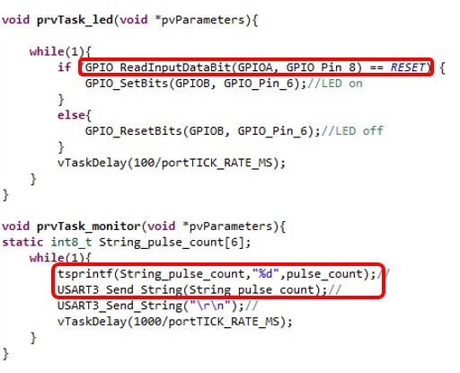
LED emission synchronized with the pulse pulse is performed by prvTask_led. An execution frequency of about 100 ms is sufficient.
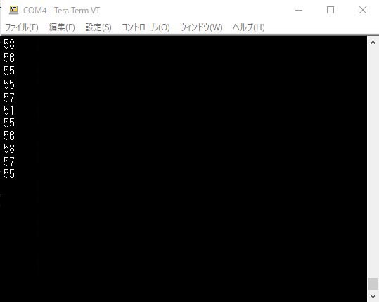
The task prvTask_monitor is used to monitor the heart rate obtained from the calculation via serial USART communication. The calculated value is converted to a string and displayed on the PC monitor every 1000 ms, and the value can be checked using terminal software on the PC side.
The photo reflector is sensitive to the way the finger is held down, but if you hold it down so that it is stable, you will see that a reasonable heart rate is displayed. The output monitor LED emits light in sync with the pulse rate.
The usage of the serial communication USART is explained in detail in "Serial communication USART [USARTdetails of STM32]" and "Serial Monitor [USART of STM32]".
The above is the basic heart rate monitor program configuration, which can be developed in various combinations, such as using PWM output dimming for LED blinking, or using WiFi for serial communication.