Serial communication SPI[SPI details of STM32]

This section explains how to use the STM32's built-in peripheral SPI. In this chapter, reading and writing data to and from an SPI-specification EEPROM is explained as an example.
Table of contents
What is Serial Communication SPI?

Serial Communication SPI is a type of synchronous serial communication. It uses four signal lines for communication: Clock (SCLK), input MOSI, output MISO, and chip select (CS).
There are master and slave devices connected to SPI; multiple slave devices can be connected to one master device on a common bus, and the target device for communication is selected by Chip Select (CS) during communication.
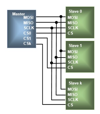
In SPI communication, the communication format varies depending on the device, but the target device is selected by the chip select (CS) signal, and usually 8-bit (1 byte) data is sent (written) as a unit of command or address, and response data from the device register is received (read). Compared to I2C communication, four wires are required, but the communication mechanism is simple and high-speed.
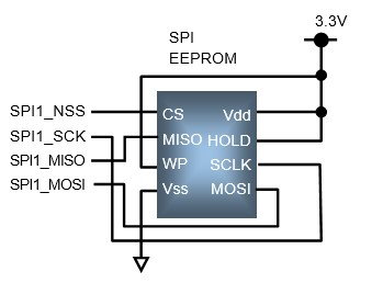
The STM32 SPI controller can be used as a master or a slave, but this section describes the SPI master using an EEPROM (Rohm's BR25G640-3). SPI is master-driven, and each time an instruction is executed, a clock is generated and 8-bit data is exchanged.
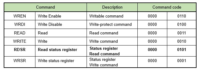
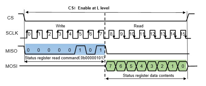
The following six EEPROM instruction modes are available. Let us look at the time chart when a status register read instruction is given. In this EEPROM, a write (MISO) instruction is synchronized with the rising edge of the clock (SCLK) and a read (MOSI) instruction is synchronized with the falling edge of the clock (SCLK) and is read into the device. Sending the Read Status Register (RDSR) command code returns status data in the next 1-byte (8-bit) unit.
When reading/writing memory data, read (READ) and write (WRITE) command codes are sent and received as a set with the address (2 bytes) of the memory for data storage divided into upper and lower bytes each. The EEPROM address in this example is 2 bytes, but it may vary depending on the device.
SPI initialization procedure
First, initialization is explained as for other peripherals.
Purpose: SPI to be used is PB3-5 with SPI1
■ CS: PE0
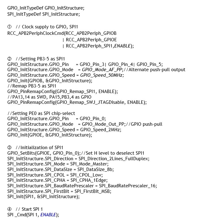
① Clock supply to GPIO and SPI1
Supplies clocks to the GPIOs used and to SPI1, which is connected to the APB2 bus and therefore supplies clocks to APB2.
② GPIO setting
The ports used for SPI1 are SCK, MISO, and MOSI, with PB3-5 designated as alternate push-pull outputs. Here, GPIO_PinRemapConfig(GPIO_Remap_SPI1, ENABLE) is executed to remap and set PB3-5 and PA15 to SPI1.
Of these, PA15 is not used when the STM32 SPI_NSS is used as master. In addition, PB4 and PB5 cannot be used as is because they are assigned the function of debug ports by default. Therefore, GPIO_PinRemapConfig(GPIO_Remap_SWJ_JTAGDisable, ENABLE) is executed to release them to normal GPIO ports. This process is not necessary if the default SPI is used instead of remapping.
For chip select CS, PE0 is set to normal push-pull output.
③ SPI initialization
Perform the initial setup for SPI . First, at the beginning of initialization, set the target chip select CS (PE0) to a "H" level so that SPI is not accepted.
Execution Example of SPI initialization function: SPI_Init(SPI1, &SPI_InitStructure);
The first argument of the function is the SPI to be set (SPI1-3: depends on the microcontroller), and the second argument is a structure member, as shown below.
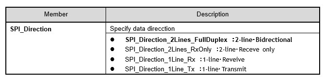
The SPI_Direction member specifies the data direction. Normally, 2-wire and full-duplex are specified.
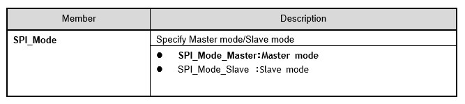
The SPI_Mode member specifies the SPI mode. Here, the master mode is specified.
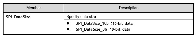
The SPI_DataSize member specifies the data size. Here, 8-bit data is handled.
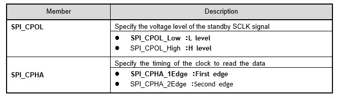
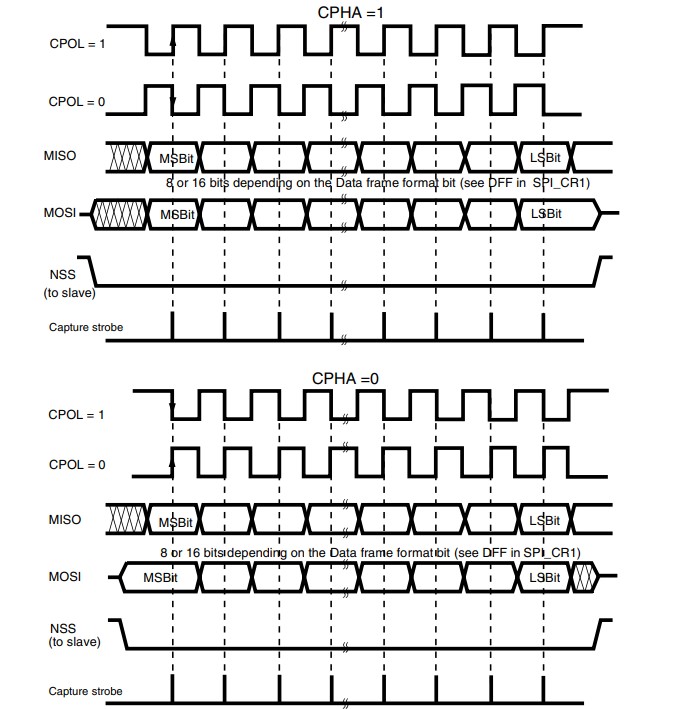
The SPI_CPOL member specifies the signal level of the waiting SCLK, and the SPI_CPHA member specifies the clock timing at which data is read. To read data on the rising edge of the clock, the signal level of the SCLK in standby mode should be set to "L" and the data should be read at the first edge timing.
The SPI_CPOL member refers to the polarity of the clock and the SPI_CPHA member refers to the phase of the clock. The combination of these members sets the SPI communication mode, called the SPI mode. The available modes are limited depending on the device on the slave side, so set them appropriately.
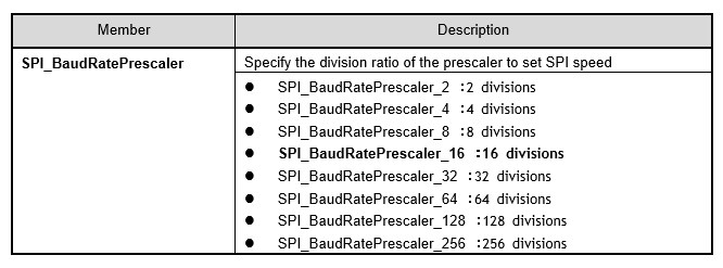
The SPI_BaudRatePrescaler member specifies the division ratio of the prescaler to set the communication speed. For example, if division by 16 is specified, the clock supplied to SPI will be 4 MHz when PCLK2 is 72 MHz. The maximum clock speed is defined by the EEPROM specification, so specify a clock speed that does not exceed it.
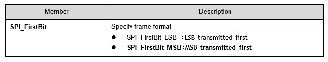
The SPI_FirstBit member specifies whether data transmission is to be performed MSB first or LSB first. Normally, MSB first is specified.
④ Enable SPI1
Now that SPI communication has been initialized, execute SPI_Cmd() to enable SPI communication.
Execution Example of SPI initialization function: SPI_Cmd(SPI1, ENABLE);
The first argument of the function specifies the SPI (SPI1-3: depends on the microcontroller) to be set, and the second argument is ENABLE to enable or DISABLE to disable.
SPI Byte Sending/Receiving
After initialization of the SPI controller is completed, communication can be started arbitrarily in the application program. When multiple devices are connected to a common SPI bus, the target device is selected by the CS signal for each communication, and the selection is deselected when communication is executed and terminated.
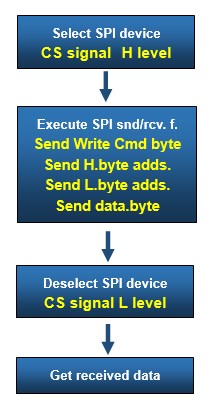
Let's look at the flow of sending and receiving 1-byte data, which is the most basic type of SPI communication.
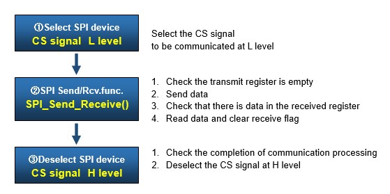
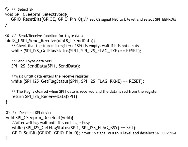
① SPI chip select
Selects the CS signal of the SPI device to be communicated with by setting it to a "L" level.
② SPI send/receive functions
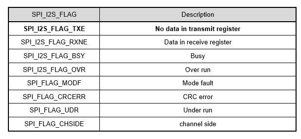
SPI_Send_Receive() summarizes the procedure for sending and receiving 1-byte data. Before starting to send data, check the send status flag (SPI_I2S_FLAG_TXE) of SPI_I2S_GetFlagStatus() to see if the previous transmission has been completed. When the flag becomes SET, the transmit register is empty.
As soon as ready to send, SPI_I2S_SendData() sends 1-byte data. The first argument of the function specifies the SPI (SPI1-3: depends on the microcontroller) to be set, and the second argument specifies the 1-byte data to be sent.
When data is sent, data is returned from the other party and entered into the receive register at the same time, but whether or not it is entered is checked with the receive status flag (SPI_I2S_FLAG_RXNE) of the SPI_I2S_GetFlagStatus function. When the flag becomes SET, it means that there is data in the receive register.
When ready to receive, SPI_I2S_ReceiveData() is executed to obtain the received data. This function returns the last data received by the SPI. The argument of the function specifies the SPI (SPI1-3: depending on the microcontroller) to be set. When data is read, the receive flag is automatically cleared.
The master and slave sides communicate data In SPI, the master and slave sides communicate data simultaneously according to the generated clock. When the master is transmitting a 1-byte command, the slave side returns 1-byte data of 0x00 or 0xFF and stores it in the receive register at the same time. Therefore, SPI_Send_Receive() includes the process of clearing the receive flag and retrieving the received data. The return value of the received data is not used for transmission.
③ SPI device deselection
After communication is completed, the CS signal of the SPI device to be communicated is set to a "H" level to deselect it. Before doing so, check the busy status flag (SPI_I2S_FLAG_BSY) of SPI_I2S_GetFlagStatus() to confirm that communication is complete and the device is not busy. When the flag is SET, the device is busy, so it waits.
EEPROM write
So far we have sSo far we have seen the flow of 1-byte data transmission and reception. In actual sending and receiving, for example, when writing and reading EEPROMs, the command and address are sent sequentially by combining the send/receive function SPI_Send_Receive() that we have created, and then data is sent and received.
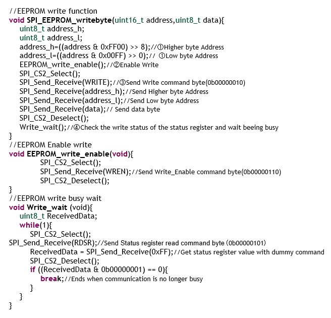
Let's create our own SPI_EEPROM_writebyte() dedicated to EEPROM writing.
Executing Example of SPI_EEPROM byte data write function:
SPI_EEPROM_writebyte(Address, Data);
Since this EEPROM has a 16-bit address, define a function in which the first argument of the function specifies the 16-bit address and the second argument specifies the 1-byte (8-bit) data to be stored. A series of procedures for sending multiple bytes of data, including the write command byte, address byte, and data byte, are summarized in the function.
① Device address
Since data communicated by SPI is in units of 1 byte, the address to be specified is separated into the upper and lower addresses for 1 byte in the function.
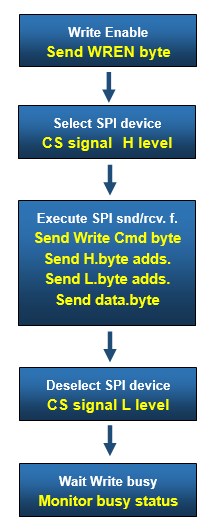
② Write Enable
For writing, it must be set to write-enable, which is done before writing, as summarized in EEPROM_write_enable(). Even if you do not bother to put it into a function, you can send the EEPROM enable command byte WREN before the write command byte WRITE in SPI_EEPROM_writebyte().
③ Send write command byte
Send the write command byte WRITE, the upper address, the lower address, and the byte data to be stored, in that order.
④ Standby by status register
Since writing takes some time, it is recommended to send the status register read command byte RDSR and wait until bit 0 of the status register obtained by sending RDSR is no longer busy, as summarized in Write_wait().
EEPROM read
The procedure for reading an EEPROM is almost the same as for writing, but it is not necessary to send a write permission command. As in the case of writing, the address is separated into upper and lower levels. In the case of reading, data is taken from a register into temporary memory and passed as the return value of the function.
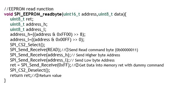
Let's create our own SPI_EEPROM_readbyte() specifically for reading EEPROM.
Execution Example of SPI_EEPROM byte data read function:
Data = SPI_EEPROM_readbyte(Address);
The first argument of the function specifies the 16-bit address that contains the data to be read.
① Read command byte sent
Send read command byte READ, upper address, and lower address byte data in this order.
② Dummy byte sent
To get data out, send some byte data, and SPI_Send_Receiver() will retrieve the received data as the return value, and work on a temporary memory ret.
③ Receive data acquisition
If the temporary memory ret is the return value of SPI_EEPROM_readbyte() after SPI device deselection, byte data can be obtained by executing this function every time it is read.
SPI is often used as an interface between ICs and MCUs. I introduce the example of SPI EEPROM in "SPI communication application[SPI of STM32]" and explain how to use the LAN controller with SPI interface "Microcontroller Ethernet-enabled system design [STM32Nucleo]".