DMA (Direct Memory Access) [DMA details of STM32]

Although DMA is not an essential skill for beginners or novice users, it may be required in practice because DMA reduces the CPU load, allowing CPU capacity to be used for other processing and contributing to power savings. In this chapter, I explain how to use DMA to transfer multiple channels of data from an AD converter to memory and how to use DMA to send and receive USART data.
Table of contents
STM32 DMA transfers

DMA is called Direct Memory Access, and data is usually transferred to memory via the CPU, whereas DMA transfer transfers register data from AD converters, serial communications, and other peripherals to memory without going through the CPU.
The replacement for the CPU is called a DMA controller, of which the STM32 MCU has at most two built-in.
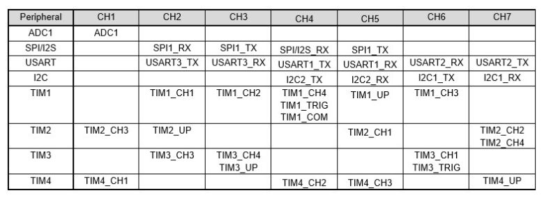
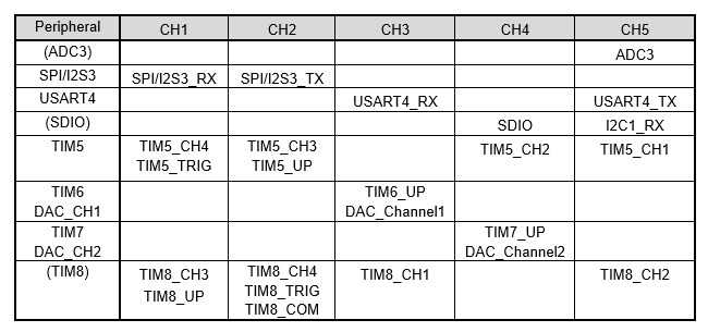
The STM32F10x has two controllers, DMA1 and DMA2, connected to the AHB. Each DMA has multiple channels and is pre-specified for each peripheral.
Data transfer by DMA for multi-channel ADCs
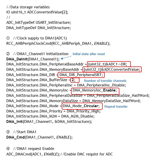
The following is an example of using DMA to acquire the conversion values of CH1 and CH2 of ADC1.
① Clock supply to DMA used
ADC1 supplies clock to DMA1 to be used as DMA request is issued to CH1 of DMA1. DMA is connected to AHB, so it supplies the AHB.
Setting Example: RCC_AHBPeriphClockCmd(RCC_AHBPeriph_DMA1, ENABLE);
The first argument specifies the peripheral to be connected to the AHB as shown in the table below.
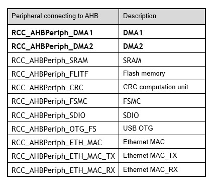
The second argument of the clock supply function RCC_AHBPeriphClockCmd is ENABLE to start the supply and DISABLE to stop the supply.
② DMA1_CH1 initial setting
Since ADC1 uses channel 1 of DMA1, initialize DMA1_CH1. DMA_Deinit() is used to restore the initial state immediately after reset. The function argument specifies the DMA channel (DMAx_Channely) to be set (x:1-2, y:1-7).
Execution Example of DMA1 Initialization function setting:
DMA_Init(DMA1_Channel1, &DMA_InitStructure);
Initialization is performed by executing DMA_Init(). The first argument of the function is the same as that of DMA_Dinit(), and the second argument is a structure member, as shown below.
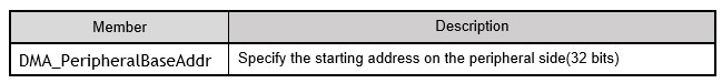
Specify the address of the data register (ADC_DR) on the peripheral side where the conversion data is stored.
This should be specified by the register name (DR) of the address of ADC1 defined in the peripheral library stm32f10x.h. The actual address may be specified directly by the one described in the reference manual ((uint32_t)0x4001244C).
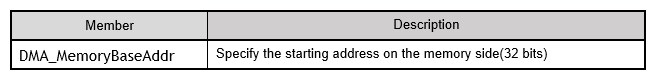
Specifies the address on the memory side where the conversion data will be stored. In this example, &ADCConvertedValue is specified as the address of the array variable ADCConvertedValue[2].
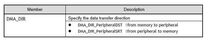
Specifies the data transfer direction; DMA_DIR_PeripheralSRT is specified for memory from the AC converter's conversion value register.
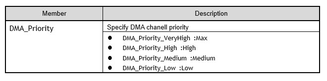
The priority of the DMA channel should be specified as DMA_Priororithm_High (high).
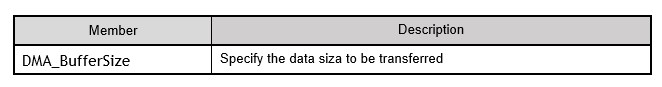
Specifies the number of data to be transferred, 2 for 2 channels.
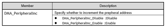
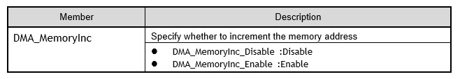
DMA_PeripheralInc and DMA_MemoryInc automatically increase the memory address for each transfer during data transfer.
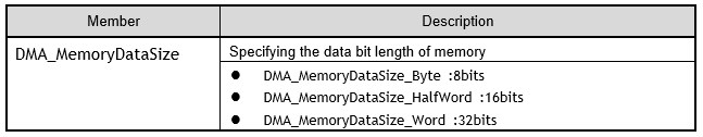
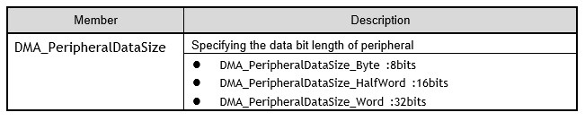
DMA_PeripheralDataSize and DMA_MemoryDataSize specify the data bit length of the peripheral and memory, respectively. Since the data length handled by the ADC is 16 bits, HalfWord is specified.
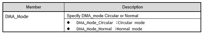
When the circular mode is specified, data in the specified number of channels is automatically and repeatedly transferred to the specified memory address.
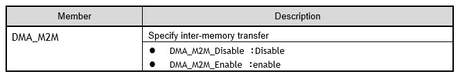
Enable when transferring from one address in memory to another address in memory, rather than between peripherals and memory. Not used in this case.
The initialization function DMA_Init(DMA1_Channel1, &DMA_InitStructure) is executed since the specification of each member has been completed.
③ Enable DMA1
Now that the DMA has been initialized, execute DMA_Cmd() to activate the DMA.
Execution Example of DMA enable function: DMA_Cmd(DMA1_Channel1, ENABLE);
The first argument specifies the channel (DMAx_Channely) of the DMA to be set (x:1-2, y:1-7), and the second argument is enabled with ENABLE and disabled with DISABLE.
④ Enable DMA1 request
At this point, the initial setting for DMA is complete and the system is in standby since it has been enabled. To actually start transferring data, it is necessary to enable DMA requests from each peripheral to initiate DMA transfers. In the example, ADC_DMACmd() is executed to start the transfer simultaneously with the conversion of channel 1 and channel 2 of ADC1 of the AD converter.
Execution Example of DMA request enable function: ADC_DMACmd(ADC1, ENABLE);
The first argument of the function specifies the AD converter to be set (ADC1-3: depends on the microcontroller), and the second argument is enabled with ENABLE and disabled with DISABLE.
This will automatically and repeatedly transfer the conversion values to the specified memory at the same time as the conversion of two channels in the AD converter.
DMA transfer for serial communication
String receive DMA transfer
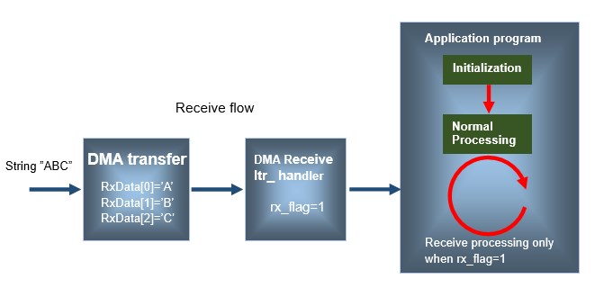
The receive program for USART communication using DMA is relatively simple. Here is an example that automatically transfers 6 characters of received data from the serial communication receive register to memory by DMA.
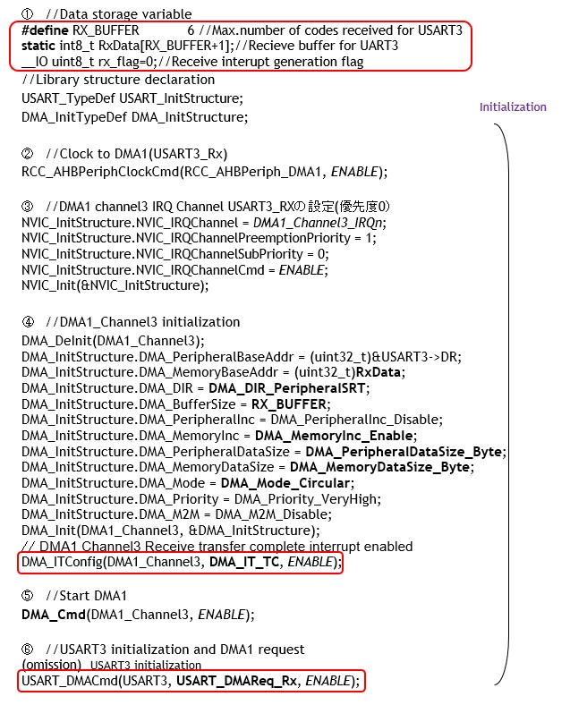
① Preparation of data storage variables, etc.
In receiving serial USART communication, prepare variables, etc., in order to set up a DMA setting to transfer 6 characters (6-character string). Here, the array RxData[] is filled with the receive character.
② Clock supplied to DMA1 (USART3_RX)
In USART3 Receive, the DMA request is given to CH3 of DMA1, so the clock is supplied to DMA1, and since DMA is connected to AHB, the clock is supplied to AHB.
③ IRQ interrupt setting for DMA1_CH3 (USART3_RX)
This time, the priority is set to use an interrupt when received data has been transferred to memory by DMA (priority 0).
④ DMA1_CH3 initial setting
Initialize DMA settings; the address of the destination memory RxData[], the number of transfers RX_BUFFER, and the DataSize, set to Byte since the transfer data is 8 bits per character. Reception is assumed to be in circular mode. In this way, the ring buffer returns to the beginning when the buffer is full after receiving data.
After setting the parameters to the structure members, DMA_Init() is executed as in the case of ADC.
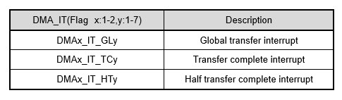
The transfer completion interrupt is enabled in DMA_ITConfig() in order to process an interrupt when the DMA transfer is completed.
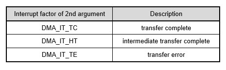
Example of enabling DMA transfer completion interrupt: DMA_ITConfig(DMA1_Channel3, DMA_IT_TC, ENABLE);
The first argument specifies the DMA channel (DMAx_Channely) to be set (x:1-2, y:1-7), the second argument is the interrupt generation factor, and the third argument is ENABLE to enable interrupts or DISABLE to disable them.
⑤ Enable DMA1
The transfer completion interrupt is enabled by the DMA_ITConfig function in order to perform interrupt processing when the DMA transfer is completed.
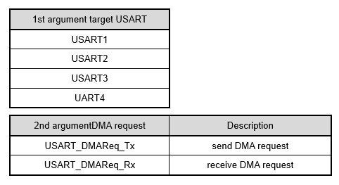
⑥ USART3 Setting and enable DMA1 (USART3_RX) request
After initializing USART3, enable DMA request to start DMA transfer. The USART DMA request is performed by USART_DMACmd(). The first argument of the function specifies the USART to be configured, the second argument specifies the DMA request to be configured, and the third argument is enabled with ENABLE and disabled with DISABLE.
From this, data is automatically transferred to memory RxData[] each time a reception occurs on serial USART3.
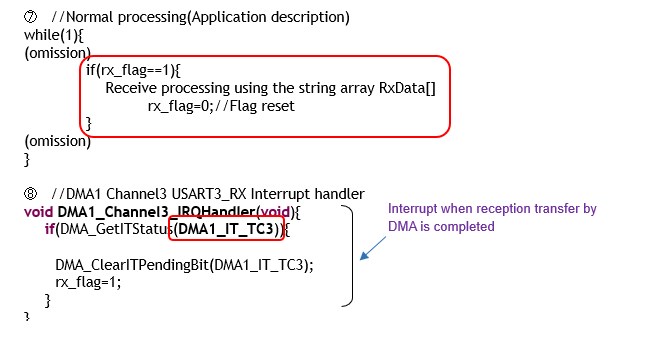
⑦ Normal in-app processing
The process of obtaining the desired string after a receive interrupt occurs is created in the application. In this example, the rx_flag is set to 1 only when an interrupt occurs, and processing is performed accordingly.
⑧ DMA interrupt handler
When a transfer is completed by DMA, an interrupt is generated and the interrupt handler DMA1 Channel3 USART3_RX is started. When this interrupt handler is invoked, DMA_GetITStatus() is executed to determine if the interrupt factor is transfer completion.
Execution Example of DMA interrupt enable function: DMA_GetITStatus(DMA1_IT_TC3);
Again, the interrupt flag should be cleared (set to 0) with DMA_ClearITPengingBit(). As for interrupt processing, setting the interrupt discrimination flag rx_flag to 1 allows the application to perform receive processing only when the discrimination flag is 1.
DMA interrupt flag (pending bit) clear function: DMA_ClearITPendingBit(DMA1_IT_TC3);
Of course, if you want to do processing strictly at the time of the interrupt, write the processing in the interrupt handler, but be careful not to do too large and heavy processing.
String transmission DMA transfer
String transmission using DMA is explained using a basic example that does not use interrupts. Although this is a simple transmission program, it shows how DMA works.
First, prepare an array TxData[] to store the strings to be transferred. Here, the number of characters (number of arrays), or Buffer_Size specified for DMA, is specified for each transmission according to the character string. The difference from the receiving case is that the conversion mode is specified as normal mode instead of continuous circular mode.
In this case, the number of characters to be transferred (DMA_BufferSize) must be specified as the value of register DMA_CNDTRx, which manages the number of data to be transferred for each transmission. This register is incremented when a transfer is started, and returns to 0 when the specified value is reached. In Circular mode, this is repeated, but in Normal mode, if nothing is done
Therefore, in the sample program, the DMA is initialized and the transfer size is specified for each transmission. As you get used to it, you only need to specify this register value, so you can set it directly in the register, as in DMA1_Channel2 -> CNDTR= BufferSize.
Direct manipulation of registers eliminates waste, making programs lighter, faster, and more efficient. However, it is less intuitive.
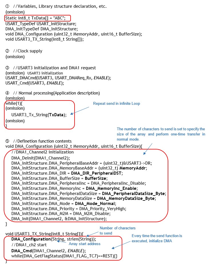
① Declaration of configuration parameters, functions, etc.
Declare configuration parameters, etc. In communication programs, the parts that handle sending and receiving are often put together in a function and then used at arbitrary times in the application, so declare the function to be created.
②③ Declaration of configuration parameters, functions, etc.
Clock the peripherals to be used and initialize them, including GPIOs.
④ Normal processing in the application
String transmission is performed in the application program itself. The sample simply displays an infinite number of registered characters, but you can see the operation of DMA and serial transmission functioning.
⑤ Functionalize frequently used processes
The send function created this time and the DMA initialization section used within the send function are also functionalized. The DMA_Cmd function is executed each time the send function is executed and a DMA transfer is started, and DMA_GetFlagStatus() is used to wait until the DMA transfer is completed.
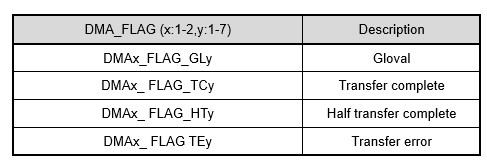
So far, I have explained serial transmission with transfer by DMA, but it is not very practical as it is because it is still waiting for the transfer to be completed here.
When DMA transfer is used, it is not very useful unless the burden on the CPU is reduced.
The application programs using the actual materials contain practical know-how, so please take a look at them and try to develop them further.