ESP32 makes STM32Nucleo easily WiFi-enabled
Explains how to make STM32 WiFi-enabled using the wireless module ESP32 (ESP32-WROOM-32). Although ESP32 module is very popular and there are many explanations to operate ESP32 itself as MCU, there is little information to easily convert other MCUs to WiFi. Then I tried to realize remote operation by AT command of serial communication relatively easily.
Table of contents
Wireless module ESP32

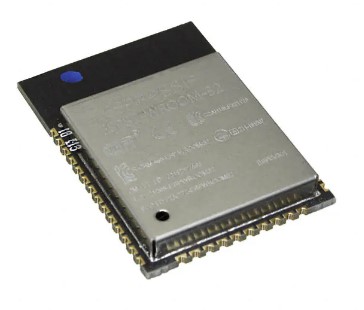
The first thing that comes to mind for converting an embedded system to IoT is WiFi using a wireless module. Among the various wireless modules available, I have decided to use the ESP32-WROOM-32, which is commonly used in electronic works as one that can use WiFi via serial communication, and integrate it into the STM32 microcontroller to make it WiFi.
The ESP32 is a wireless module that supports WiFi and Bluetooth, but is itself a high-performance MCU that can be programmed using the Arduino development environment, which is popular for electronic construction. Here I will not involve Arduino, but treat it as a wireless module.
Explains how to make a Nucleo board (STM32 MCU) WiFi IoT-ready using the ESP32 wireless module. The ESP32 module (ESP32-WROOM-32) is very popular, and there are many explanations about how to operate the ESP32 itself as MCU in the Arduino development environment. However, there is little information about how to easily convert other MCU systems to WiFi, and then I have tried to summarize with a relatively simple STM32 WiFi conversion.
After much research, I found out that when using the module as a wireless module, it is sufficient to send "AT commands" via serial UART to set the module mode and acquire data. The ESP32 cannot use this AT command immediately after purchase, and firmware (for AT command) must be written.
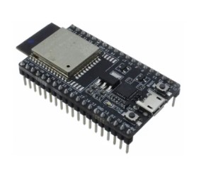
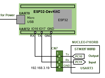
This firmware is written to the module via serial UART from a PC. If you are new to this, we recommend using the ESP32-DevKitC, which includes a USB serial conversion module. This board can be powered from a micro USB port and has a regulator to convert 5V USB bus power to 3.3V power supply for ESP32, making it easy and convenient to use.
Firmware for AT Commands
I found out that I can control ESP32 from PC or MCU via serial UART by using AT command for WiFi communication, so we will make ESP32 module AT command compatible by the following procedure to enable using AT command.
- Download Firmware for AT Commands
- Write firmware with flash writing tool (micro USB UART0 port)
- Confirmation of AT command operation with PC terminal emulator (USB-UART conversion cable UART2 port)
I will not provide a detailed explanation of the procedure from downloading the firmware for AT command to checking the AT command operation, as this is not the purpose of this site. Please refer to the Internet search for "ESP32 AT command" to obtain sufficient information.
ESP32-DevKitC uses a serial conversion IC inside ESP32-DevKitC to communicate data via serial UART with a PC USB port. This IC is implemented with "CP2102" from SILICON LAB, so a driver is required to control it. If the USB port is not recognized when ESP32-DevKitC and PC are connected with USB cable for the first time, please select "VCP Download" from the "Download for xxxx" column on the OS here and download and install it.
The ESP32 also has UART1 (pin/socket SD2 RX /SD3 TX), but these pins are assigned to SPI communication by default, so they are not used.
Default settings for UART of ESP32-WROOM-32
For Firmware transfer USART0:RXD0 RX/TXD0 TX
For AT command USART2:IO16 RX/IO17 TX
Baud rate:115200bps / Data siza:8/ Parity:None/ Stop bits:1
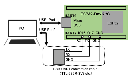
After transferring the firmware for AT commands, the PC can communicate with the ESP32 via AT commands. Note that UART0 of ESP32 is for writing such as firmware transfer and cannot send/receive AT commands, AT commands are communicated to UART2 via a USB-UART conversion cable.
You can use whatever PC terminal emulator you are familiar with, but we use "TeraTerm" on this site. Set the serial communication settings to the default (Baud rate:115200bps / Data siza:8 / Parity:None / Stop bits:1) in EPS32. In "Settings"-"Terminal", please set the line feed code as CR+LF so that the codes CR and LF will be sent when the return key is hit. Also, if you are concerned about the local echo, uncheck the "Local Echo" checkbox, as it will return the typed characters.
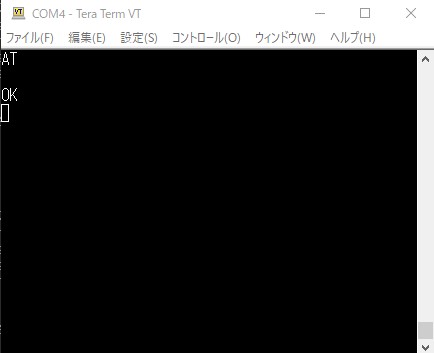
Success is obtained when you get an "OK" response when you send the command "AT" using terminal emulator that has been configured for serial communication on the PC.
The ESP32 serial UART can be changed from the default values. The current communication settings are responded to with the command AT+UART_CUR? To change it, give parameters, for example, command AT+UART_DEF=9600,8,1,0,0. The details are described in the ESP32 AT Command Instruction Set (ESP32 AT Instruction Set).
Note: Be careful not to set incorrect values, as doing so may result in communication failure.
STA (Station) mode
To begin with, we will set up the ESP32 as a STA (station) mode for WiFi.
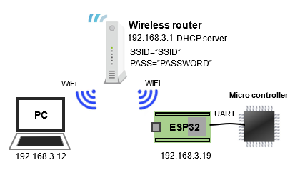
STA (Station) mode is a mode in which the ESP32 functions as a terminal that is assigned an IP address by a wireless router (DHCP server). In this example, we assume that an IP address of 192.168.3.19 is given.
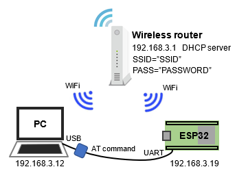
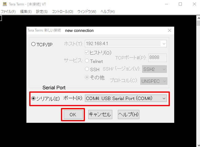
Run the terminal software on your PC and select the virtual serial port (COM4 in the following case) that is recognized when the USB serial converter cable is connected to the PC. This is not the USB port on the ESP32-DevKitC that was used when the firmware was written.
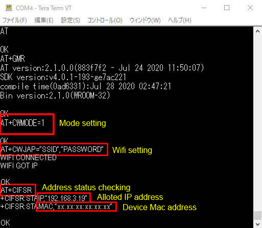
I will now send the main AT commands from the terminal to the ESP32 to write the mode and check the response. First, try sending the command AT+GMR; the ESP32 will respond with the AT firmware version.
Then send the command AT+CWMODE=1 to put the ESP32 into STA mode." 1" is STA mode.
Now that the ESP32 is in STA (station) mode, send the command AT+CWJAP="SSID", "PASSWORD" to join the network. Enter the SSID name and Encryption key according to the wireless router you are using.
When you receive a "WIFI CONNECTED" response, you are connected to the wireless router (joined the LAN). To check the assigned address status, send the command AT+CIFSR and the IP address and MAC address will be responded.
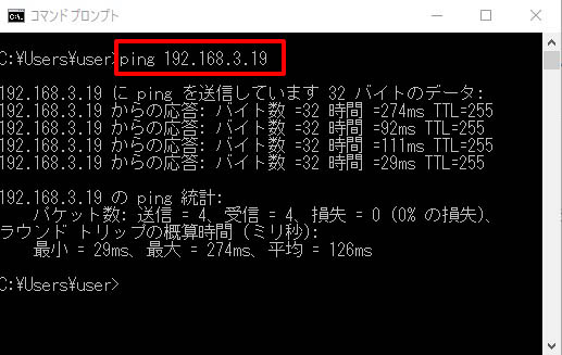
Now let's verify the connection by running the ping command to confirm that the IP address assigned at the PC command prompt is valid. The command prompt can be found by selecting "Command Prompt" in "Windows System Tools" in the Windows Start menu or by typing cmd.exe in the menu search.
Enter the assigned IP address after the ping command, e.g. "ping 192.168.3.19", and if the address is valid and you can connect to the network, you will get a response like the one below. This means that the PC and ESP32 are connected via a router. This is called "ping" when the connection is open to the network. The command ping is often used to check the connection status of a device.
STA mode setting summary
- Set to STA mode with command AT+CWMODE=1
- WiFi setting with command AT+CWJAP="SSID", "PASSWORD
AP (access point) mode
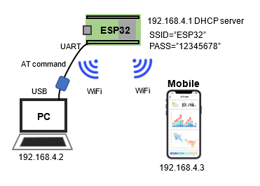
In STA mode, the user participates as a terminal in a network that uses a wireless router at home as an access point. Now let's try setting up an AP (access point) mode in which the ESP32 itself becomes an access point.
In this mode, ESP32 itself acts as a DHCP server that assigns IP addresses to other client network devices as a master access point even when WiFi is not available.
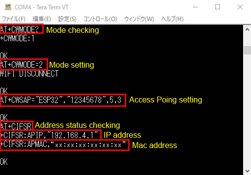
As with the STA mode setting, after starting the terminal software on the PC, first send the command AT+CWMODE? to confirm the current mode. If the response is "1", it is STA mode, and if the response is "2", it is AP mode. (This command is only for confirmation).
To put the ESP32 in AP mode, send the command AT+CWMODE=2. "2" is read as softAP mode in ESP32 in AP mode.
Set the access point SSID name and encryption key, etc. (optional) in AP mode. The command AT+CWSAP="ESP32", "12345678",5,3 is the SSID name, encryption key, wireless LAN channel, and cipher type in this order.
The last cipher type, 3, is WPA2_PSK. The others are 0:open/1:WPA_PSK/4:WPA_WPA2_PSK.
The encryption key must follow the rules for the encryption type; an error will occur if the encryption key is less than 8 characters when WPA2_PSK is specified.
To check the assigned address status, send the command AT+CIFSR and the IP address and MAC address will be responded, so you can check the IP address as the network ID.
Now that you have created a new ESP32 WiFi access point (SSID:ESP32), connect your PC to the "ESP32". If the connection fails, delete the "ESP32" access point and try again.
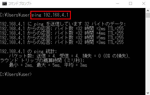
Once you have connected to the ESP32 WiFi access point, check to see if the ping is going through at the command prompt. If the following response is returned, the connection was successful.
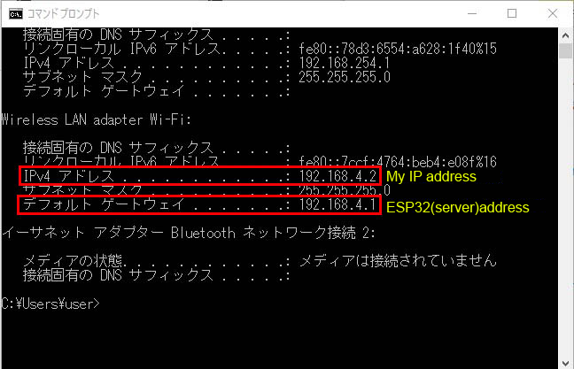
To check the IP address assigned to your PC by the ESP32 WiFi access point, run the command ipconfig at the command prompt. You will get back your IP address information as shown below, indicating that ESP32 has assigned an IP address to the client PC as a DHCP server.
AP (access point) mode setting summary
- Set to AP mode with command AT+CWMODE=2
- WiFi setting with command AT+CWSAP="ESP32","12345678",5,3
Communication between ESP32 and PC as TCP server
So far, we have configured a wireless LAN environment in which the ESP32 is set to STA mode or AP mode and can communicate with other devices (e.g., PCs) on the same LAN (same default gateway) in the same position as a client or server.
In this state, the ping passes and it is confirmed that they are on the same network, but they cannot communicate within the LAN with each other yet. In order to communicate with ESP32, it is necessary to establish a relationship between the server and the client for communication.
Here, I will configure the EPS32 as a TCP server, create a system that is accessed wirelessly from terminal software using PCs and smartphones in the same LAN as clients, and explain the settings for basic TCP communication in the LAN.
Once TCP communication is enabled, for example, by specifying the IP address and port using PC terminal emulator, strings can be exchanged as in serial communication.
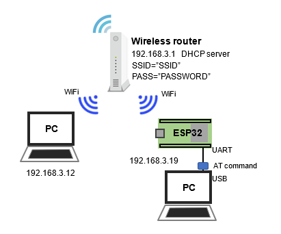
The system configuration is basically the same as before, but in this case, the PC that exchanges AT commands with ESP32 via serial USART is explicitly separated from the PC that is used as a network client in the LAN. In fact, they may be shared.
TCP Server Settings
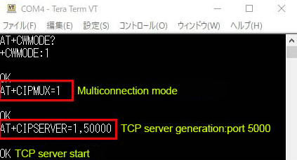
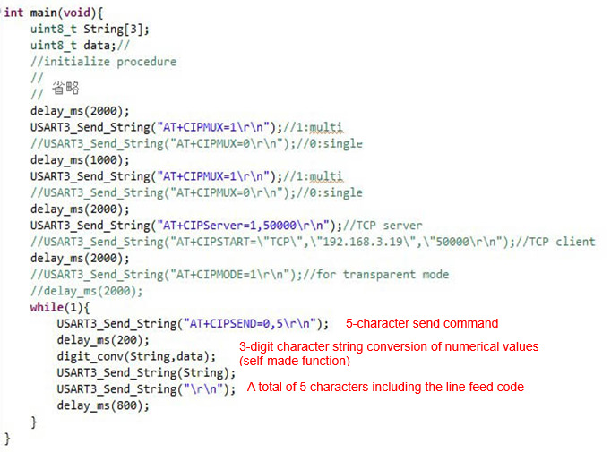
When setting up a TCP server, first set it to a mode that can support multiple connections (multi-connection mode). The command AT+CIPMUX=1 is "1": multi-connection, "0": single-connection mode. The ESP32 defaults to single connection mode, so be sure to execute this command.
The command AT+CIPSERVER=1,50000 creates a TCP server. The first value of "1" creates a server, and "0" deletes a server. The second value is the port number of the TCP server. The second value is the port number of the TCP server. The TCP server is now waiting for a connection from the client side.
Start terminal emulator on the client side, such as a PC, and connect to the server side by specifying the IP address and port number of the host (TCP server).
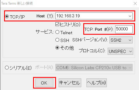
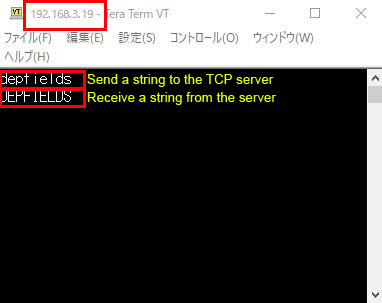
The connection is successful when the IP address of the TCP server is displayed at the top of the terminal.
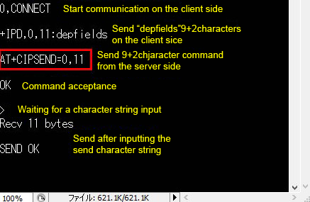
Let's quickly send a string from the terminal to the TCP server side. Type the 9 characters of "depfields" and press the Enter key, and you have sent 11 characters, including the newline code. In this example, the terminal is set to local echo, so the characters you entered appear.
On the TCP server side, when a character is received from the client side, the message "+IPD,0,11:depfields" is displayed. +IPD indicates that it is incoming data, and the connection ID is 0, meaning that a total of 11 characters including strings and newline codes have been received.
Next, let's try sending a string from the AT command operation terminal on the TCP server side. AT+CIPSEND=0,11 is a command to send 11 characters to the link with connection ID 0. This is for sending 9-character data including 2 newline codes. If the command is accepted, "OK" is returned and the > prompt is displayed, waiting for input.
The string is sent to the terminal by pressing return with "DEPFIELDS" in uppercase. After the message "Recv 11bytes" is displayed, "SEND OK" response indicates that the transmission was successful.
The client terminal should display the string "DEPFIELDS" that was sent.
Summary of TCP server settings
- Set the command AT+CIPMUX=1 to set multi-connection
(Must be multi-connection for TCP servers) - Generate TCP server port xxxx with command AT+CIPSERVER=1,xxxx
This time, I used AT commands to control ESP32 from a PC to make it a TCP server and then communicate with a TCP client PC. Next, I will try a system in which MCU operates AT commands to set ESP32 as a TCP server and wirelessly control it from a client PC or smartphone instead of a PC.
Before that, there are cases where ESP32 can be used as a TCP client, which we will explain. This is used when accessing a server in the cloud, for example.
TCP Client Configuration
ESP32 can be configured as a TCP client. This is used for applications that operate from a browser on the web by accessing an HTTP server that uses the HTTP protocol, which is a higher level of communication protocol than TCP socket communication.
When configured for a TCP client, set to a mode that can support a single connection (single connection mode). The command AT+CIPMUX=0 is "0": multi-connection, "0": single connection mode; ESP32 defaults to single connection mode.
The command AT+CIPSTART="TCP", "xxx.xxx.xxx.xxx.xxx",80 creates a TCP client, the first is the protocol, the second is the HTTP server address on the web and the third is its port number. With the response "OK," the TCP client is started.
In single-connection mode, a transparent mode can be used, which allows the exchange of data like normal serial communication, regardless of AT commands. To do this, execute "AT+CIPMODE=1".
Thereafter, when you send "AT+CIPSEND" to send a string, you will be in transparent mode and can communicate with the web server using HTML code. The transparent mode is terminated when "++++" is received.
Client Configuration Summary
- Single connection setting with command AT+CIPMUX=0
(Must be single connection for TCP clients) - Generate TCP client with command AT+CIPSTART="TCP", "xxx.xxx.xxx.xxx.xxx",80
- Set to transparent mode with command AT+CIPMODE=1
Connection between MCU and ESP32
Once the firmware for AT commands has been transferred to the ESP32 and it can communicate with the PC via AT commands, the next challenge is to communicate with MCU instead of the PC.
From a terminal on a PC, I can now send AT commands to communicate with ESP32, but how can I exchange AT commands from another execution environment, a microcontroller, to, for example, open a TCP communication port in the terminal?
This is also easy once you understand it, but if you want to know the secret, all you have to do is to send and receive AT commands themselves as character strings via serial USART, just as you do in a PC terminal.
This is also easy once you understand it, but if you want to know the secret, all you have to do is to send and receive AT commands themselves as character strings via serial communication, just as you do in a PC terminal.
Steps to open a TCP server using a microcomputer program
The settings for the operation mode are written to the flash until the ESP32 is set to STA mode or AP mode with the AT command and passes the ping of the wireless LAN environment, so the settings are the same in any environment.
When using MCU, the connection mode setting is automated by MCU program.
This is a sample of setting ESP32 as a TCP server with AT command on MCU and then sending data to a terminal every second in an infinite loop for display.
It is basically the same as setting up a serial communication terminal on a PC from terminal software, but there are some points to note to automate AT command operation in a microcontroller program.
If you execute AT commands manually from a terminal, they work fine, but if you perform the same procedure in a microcontroller program, problems may occur.
This is thought to be due to the lack of sufficient response time for command execution, etc., which prevents normal operation. In particular, there was a problem with garbled characters in the first AT command transfer executed after program startup, which prevented subsequent commands from taking effect.
To prevent this, I added a sufficient wait time before and after the AT command, and then executed the first command twice as a fail-safe just to make sure the problem was avoided, and it worked correctly.
When executing AT commands with MCU program for the first time, you should first aim to ensure that the TCP server is started and that TCP communication is opened by specifying the IP address and port you wish to access with the terminal emulator.
The point of string transmission within the application.
Once the TCP server is accessible and the port is open, you have passed the first hurdle. The next step is to exchange strings within the application.
To send a string, execute the command AT+CIPSEND=0,5 with the line feed code \r\n immediately before the string, which is called "waiting for transmission". Then, the string to be sent is executed by executing the string sending function (in this case, the UASART3_SendString function).
Even something as simple as sending a string of characters to be sent and displayed on the terminal, as in serial communication, is difficult to achieve consistently unless you know the key points. In my experience, it took more than a day of trial and error to get the same results as with serial communication when handling string transmission for the first time.
The reason for the instability was that the number of characters in the transmitted string was not constant. The reason for the instability was that the number of characters in the string was not constant. This was due to the fact that the variable numeric values calculated in the application were converted to strings before being sent to the terminal.
Try sending commands manually from terminal software for serial communication on a PC, not from the microcontroller program, in case the number of characters is off. You will see that the display is quite unstable.
To solve the problem, I created my own function (digit_conv function) that converts characters and fixes them to 3 characters when, for example, I want to send a number with a maximum of 3 digits, regardless of the number of digits in the number, and then the display became stable.
The point of String Transmission
- The command AT+CIPSEND=0,x, specifying the number of characters, should be executed immediately before the string is sent.
- The number of characters must exactly match the number of characters actually sent by the string send function (in this case, the USART3_Send_String function).
The point of string reception in the application
By receiving character strings from terminal emulator on a PC, smartphone, or other device and treating them as commands or data, MCU can be remotely controlled.
For example, when you input the string "command" in terminal software, ESP32 returns the string "+IPD,0,9:command" as a response, so the microcontroller side extracts the "command" under ":" before sending it to the application as a command or The data is processed as data.
Once the ESP32 is configured as a TCP server, it can be handled like serial communication, as strings can be communicated from remote client terminals using terminal emulator. This is the first step toward wireless microcontrollers and the IoT. TCP communication is the basis of a web server that can be operated from a web browser on the Internet, so please familiarize yourself with it first.