I2C communication application [I2C of STM32]

This application program reads and writes to the I2C specification type EEPROM of STM32 MCU. Details of the peripherals are explained in Serial Communication I2C.
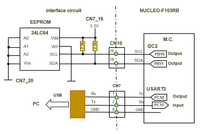

Here PB10 and PB11 are used for I2C2. Data read from memory is transferred to the monitor using USART3 for display.
The chip address of the I2C EEPROM is A0 because A0, A1, and A2 are set to 0 V as shown in the above figure. Please refer to the I2C EEPROM 24LCxx datasheet for details.
Three data (data1, data2, data3) are written to and read from the I2C EEPROM.
Immediately after program startup, the data stored in EEPROM is displayed.
Program Description
When one of the three character string commands "1@", "2@", or "3@" is entered by a PC, the data corresponding to that command is written into the EEPROM, and the stored data is read and displayed every 1000 ms cycle.
Data is rewritten each time a command is entered.
It is operated from a PC via serial UART communication to monitor the status of read/write (send/receive functions).