PWM pulse application [PWM output of STM32]
This is an application program that sets the timer of the STM32 MCU to PWM output. You can see the frequency and pulse duty ratio change depending on the setting value.

This is an application for pulse output using PWM (Pulse Width Modulation). The settings are the same as for the fixed pulse application, but the count clock is set to 1 kHz.
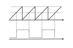
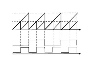
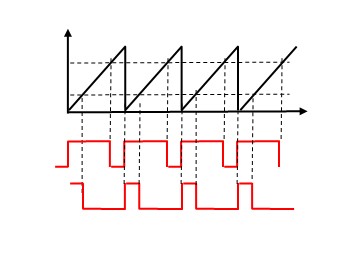
For PWM output, a variable ARR_val of 1000 generates a 1 Hz pulse, resulting in LED blinking at 1 second intervals. In the case of PWM, the ARR cycle is the pulse frequency; changing the ARR_val value will change the blinking cycle.
When the variable duty_ratio is 2, the ON/OFF ratio of output pulses is 1:1. The blinking cycle is fixed, but the lighting period changes.
Setting specification:
Pin used: PB8 Alternate output (Timer output)
Peripheral used:TIM4_CH3 Counter CLK 1kHz