Accelerometer using STM32 Nucleo

Table of contents
What is an Accelerometer?
Among various sensors, accelerometers are often used in invisible places in products, so many people may not know what they are, despite their high utilization.
For example, it is used in smartphones to change the orientation of the screen by detecting the tilt based on gravity applied to the internal acceleration sensor, and in pedometer applications that measure vibrations.
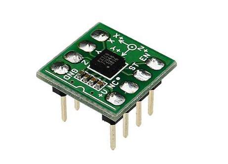
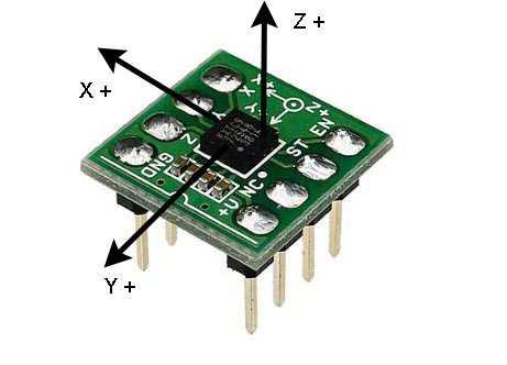
The accelerometer used in this project is the Kinox KXTC9-2050, which can detect acceleration in 3D space in the X, Y, and Z axes, and is a module equipped with a 50 Hz low-pass filter capacitor.
The detected acceleration includes not only acceleration due to motion, vibration, shock, etc., but also gravity (G) as an offset (DC component), so if the gravity component in the X, Y, and Z axes is known, the sensor tilt angle can also be detected.
Applications using accelerometers include detection of tilt due to gravity, vibration due to vibration and motion, free-fall and motion acceleration measurements, and measurement of the number of steps taken due to impact. With some ideas, it can be further developed into a variety of applications.

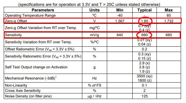
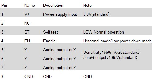
The accelerometer KXTC9-2050 can detect acceleration in the range of ±2G. From the outputs in Specification Table 1, for example, if the X and Y axes are the horizontal plane and the sensor is installed in the direction of gravity on the Z axis, the X and Y outputs should be 1.65 V because the gravity component is zero, and the Z axis output should be 2.32 (=1.65+0.66) V because it includes 1 G.
About Gravity and Acceleration
Accelerometers detect acceleration, but the signal includes a gravity acceleration component as an offset (DC component). Gravity G is a constant acceleration in the direction of the ground at 9.8[m/sec2].
Normally, acceleration occurs with motion, but this gravitational acceleration component occurs even when the sensor is in a static state. What does this mean?
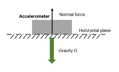
Accelerometers do not directly detect the gravitational acceleration component from the actual motion, but rather the vertical drag force against gravity. Therefore, when the sensor is made to stand still on a horizontal surface such as a desk top, the vertical drag force balanced by the gravitational acceleration G is detected as gravitational G.
Therefore, the direction of the gravity acceleration component included in the acceleration sensor output is opposite to the actual gravity, so it is included as an offset (DC component) in the acceleration of the actual operation. For example, if a free fall is made in the direction of actual gravity on the Z axis (negative direction), the Z axis component of the acceleration sensor output will be zero, or 1.65V, because the gravity offset portion due to vertical drag force is canceled.
In an application using an accelerometer, to detect tilt, it is sufficient to detect and measure only the gravity component, which is the offset of each axis, and to detect acceleration in motion, it is sufficient to detect and measure the acceleration component excluding the offset of each axis. In addition, shock is measured by the acceleration component of deceleration that occurs instantaneously.
Accelerometers are interesting sensors that can be developed for a variety of applications depending on your ideas. This time, as a preliminary step, we will create an application that monitors acceleration output for 3 acceleration axes to check what the output of the acceleration sensor is like.
Application using acceleration sensors
This time, I will create an application program to check the acceleration output as per the specifications.
Acceleration uses the STM32's AD conversion as an analog input signal. Peripheral AD conversion is explained in "AD converter [ADC details of STM32]".
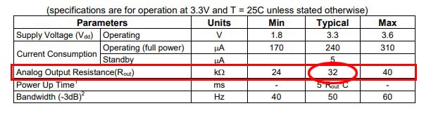
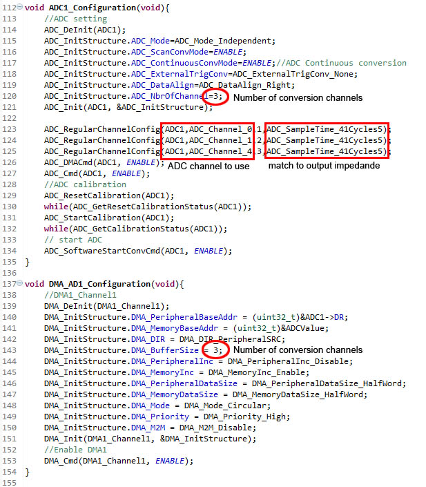
The STM32's AD conversion requires the output impedance of the sensor to be specified as an analog signal input parameter. From the manufacturer's specification table 3 (data sheet), the output impedance is 32 kΩ on average.
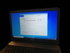
The application to monitor the accelerometer signal uses three analog inputs and serial communication to a PC. Since this AD conversion has three analog signals, it is efficient to combine it with "DMA (Direct Memory Access) [DMA details of STM32]".
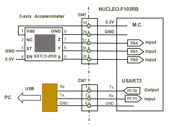
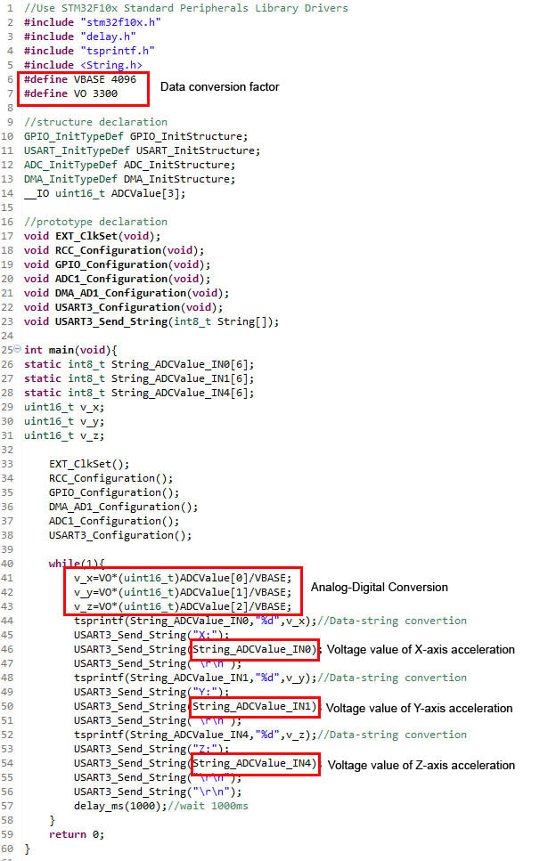
In the actual program, ports PA0, PA1, and PA4 are set to analog inputs AD1_CH0, AD1_CH1, and AD1_CH4 for X, Y, and Z axis 3-point analog signal inputs, respectively, and multiple channels of data are automatically transferred to memory by DMA with AD conversion in continuous conversion mode.
The acquired analog data is converted to voltage values (integers) and then further converted to character strings and sent via serial communication.
The initial setting of AD conversion specifies the channel to be used and the output impedance to be matched to the output impedance of the accelerometer.
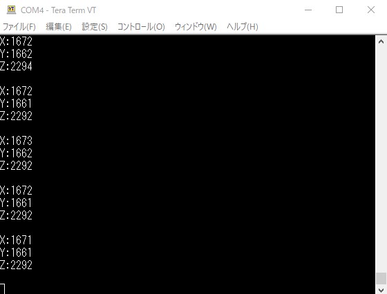
In this application, the X-, Y-, and Z-axis voltage values (integer) of the acceleration component are serially transmitted every second and monitored by a PC terminal. Since the acceleration sensor is stationary on the X- and Y-axis planes, it can be confirmed that the gravity acceleration component is added to the Z-axis as an offset component.
Since it is stationary, only the component affected by gravity (the vertical drag component) will show a change in output relative to the reference value of approximately 1.65V.
Since it is stationary, only the component affected by gravity (the vertical drag component) will show a change in output relative to the reference value of approximately 1.65V.