AD converter [ADC details of STM32]

Because the STM32 MCU's AD converters are so sophisticated, it is recommended that beginners step up to them, starting with the simplest ones and understanding them in turn.
This chapter describes the single-mode conversion method, in which a single channel analog input is manually acquired only when necessary, to the method in which multiple channels of analog input are automatically acquired in succession and transferred to memory via DMA transmission.
Table of contents
AD converter of STAM32

MCU has a built-in AD converter (AD converter), which can take analog signals into MCU and convert them into digital signals. the AD converter of the STM32 has a resolution of 12 bits, and the STM32 has a maximum of 3.3V, so 3.3V is divided into 4096 (= 212) parts. It can handle numerical values.
The STM32 AD converter has a very fast conversion speed and high performance, and is highly functional, capable of switching between multiple channels with a single AD converter circuit. Some of them have multiple AD converters, and there are several ways to simply acquire AD conversion values. In this chapter, we will explain how to use the multifunctional AD converters of STM32 MCU.
It is not necessary to master all the functions, but rather to expand the range of applications as needed. Once you know and understand how to use this too, all you need to do is apply it to your application.

Since AD converters handle analog signals, it is necessary to use them with a little awareness of analog circuits. It has an analog conversion circuit called sampling hold that uses a capacitor to convert analog signals to digital signals, and the easier the current flows during conversion, the shorter the time required to charge (store) the capacitor, and thus the faster the conversion can be performed.
Analog sensors connected to AD converters have an internal resistance, and the smaller this resistance is, the more easily current can flow, resulting in faster conversion. This internal resistance is also called output impedance, which must be known when using AD converters.
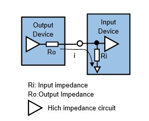
Impedance is the resistance of an AC circuit including DC, but here it is replaced by the internal resistance of DC. In the figure, the relationship between output impedance Ro and input impedance Ri of the input device should be Ro<<Ri in the AD converter circuit. This is because, considering Ri on the input side as fixed, the smaller the impedance Ro on the output device side is, the smaller the effect of voltage drop due to load current i becomes and the easier it is for current to flow to the input device side.
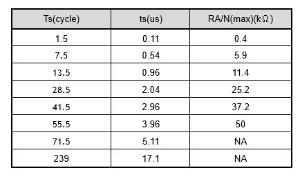
According to the STM32 datasheet, the output impedance of the device connected to the AD converter and the time required for AD conversion are shown in the table below. This shows the maximum impedance that can be connected when the supply clock of the AD converter is 14MHz. This table shows that the smaller the impedance, the shorter the AD conversion time.
Single mode, conversion on demand
First, I will summarize the overview of the STM32 MCU's AD converter and then explain the actual program as an example. The AD converter of the STM32 MCU has many more setting items than other peripherals because of its high functionality, but once you understand it at the beginning, all you have to do is block it as a module and use it in your application.
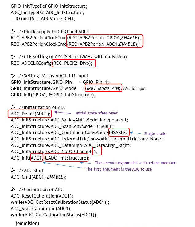
① Clock supply to ADC1
Supplies the clock to the ADC1 converter used, which is connected to the APB2 bus and therefore supplies the clock to APB2.
② ADC1 clock setting
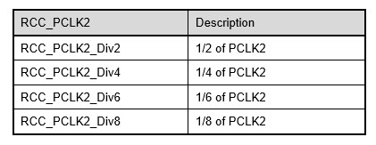
Since the AD converter is via a prescaler dedicated to the AD converter at the end of APB2, this division ratio is set with the RCC_ADCCLK function. The division ratio is specified in the RCC_PCLK2 argument of this function. Here, the frequency divider ratio is set to 1/6, and the clock to the AD converter is set to 12 MHz (72 MHz/6). The output impedance of the input device is set to 12 MHz, which is the closest to the assumed 14 MHz operating clock.
③ ADC1 input port GPIO setting
Set the input port GPIO of the ADC to be used, specifying an analog input for PA1.
④ Initial Settings for AD Converter
Initialize the AD converter. The initial ADC_DeInit function is used to restore the initial state immediately after reset. Initialization is done by executing ADC_Init().
Execution Example of AD converter initialization function: ADC_Init(ADC1, &ADC_InitStructure);
The first argument of the function specifies the AD converter to be set (ADC1-3: depends on the microcontroller), and the second argument is a structure member, as shown below.
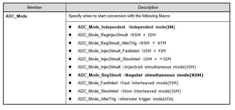
The ADC_Mode member specifies the mode when using a single or multiple AD converters. Various methods can be specified to improve conversion time efficiency: independent mode (ADC_Mode_Independent) when using a single AD converter, and dual mode when using multiple AD converters.
For example, if two ADC1 and ADC2 are used and the conversion order of the channels used is registered as a group for each AD converter, the regular simultaneous mode (ADC_Mode_RegSimult) is to perform conversions simultaneously and repeat the conversion of the next channel in sequence after conversion. There are other methods to link multiple AD converters or to match their timing, but these two modes are all you need to know for now. Details of other modes are described in the reference manual of each MCU.
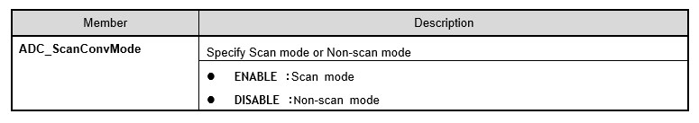
In the ADC_ScanConvMode member, one AD converter has multiple channels and the conversion order of the channels to be used, etc., are registered. Scan mode is to convert these registered channels continuously at a time, and split scan mode is to convert a fixed number of channels at a time. When multiple channels are used, the scan mode (ENABLE) should be specified.
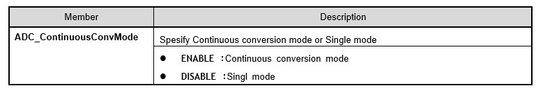
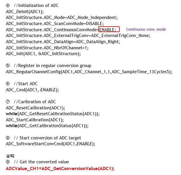
The ADC_ContinuousConvMode member has two modes: continuous conversion mode, in which conversions are performed continuously, and single mode, in which conversions are performed only when the ADC_SoftwareStartConvCmd function is given as the conversion start command.
In continuous conversion mode, once a conversion is started, the conversion repeats, so the latest conversion value can be obtained at any desired timing in the application program. In contrast, single mode is executed only when the conversion value is to be obtained, thus reducing power consumption, but the conversion takes some time, so it is necessary to wait for a certain period of time.
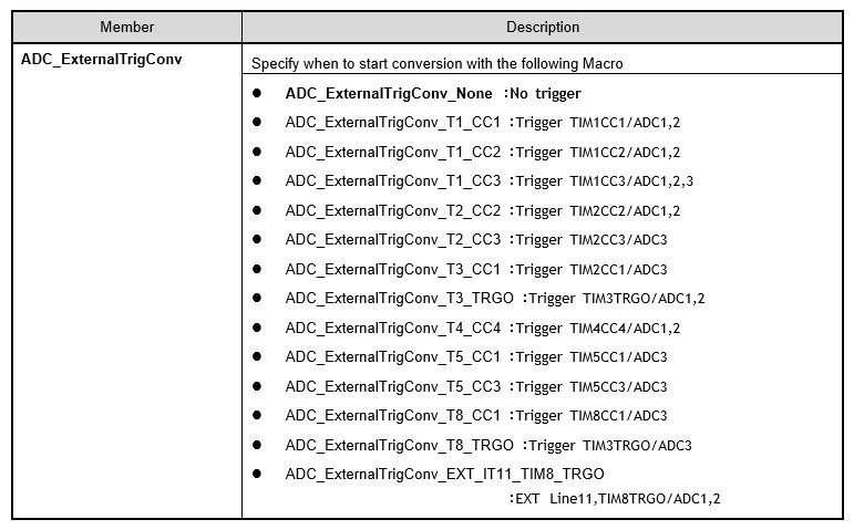
The ADC_ExternalTrigConv member is specified to determine when to start a conversion with a timer event. If not used, specify no trigger (ADC_ExternalTrigConv_None).
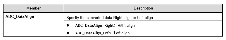
The conversion result of the STM32 MCU's AD converter is 12 bits, but the register that stores the numerical value is 16 bits, so you need to specify whether the storage method is right-justified or left-justified. Normally, the last 12 digits of the LSB side should be stored right-justified (ADC_DataAlign_Right).
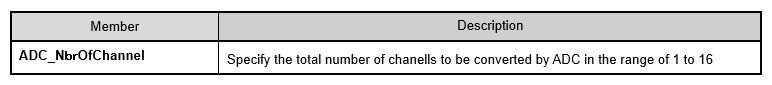
Specifies the number of channels to be used. In the sample, one channel is used, so it is set to 1.
The initialization function ADC_Init(ADC1, &ADC_InitStructure) is executed since the specification of each member has been completed.
⑤ Initial Settings for AD Converters
Now that the AD converter has been initialized, ADC_Cmd() is executed to enable the AD converter.
Execution Example of AD converter activation function: ADC_Cmd(ADC1, ENABLE);
The first argument of the function specifies the AD converter to be set (ADC1-3: depends on the microcontroller), and the second argument is enabled with ENABLE and disabled with DISABLE.
⑥ Calibration of AD converters
For other peripherals, this completes the setting but AD converters require one more step. That is calibration. This calibration compensates for individual differences among MCUs, so it should be performed every time the AD converter is initialized.
The calibration procedure first executes ADC_ResetCalibration() to initialize the calibration contents, and then calibration is executed with ADC_StartCalibration(). Since each function takes time, completion is confirmed by the status.
⑦ Start of conversion of AD conversion target
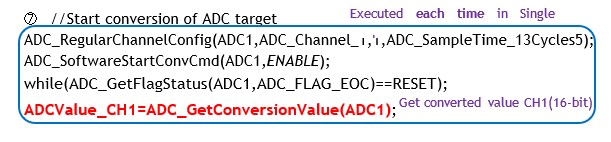
Now you can get the conversion value from the AD converter at any time. In the program example, ADC1 is in CH1 single mode, so ADC_RegularChannelConfig() and ADC_SoftwareStartConvCmd() are executed each time to start conversion.
To use an AD converter, the channels to be converted must be specified by registering them in a regular conversion group. This is done using ADC_RegularChannelConfig().
Execution Example of Regulator Conversion Group Registration Function:
ADC_RegularChannelConfig (ADC1,ADC_Channel_1,1,ADC_SampleTime_13Cycles5);
The first argument of the function specifies the AD converter to be set (ADC1-3: depends on the microcontroller), the second argument specifies channels 0 to 17 (ADC_Channel_1 - ADC_Channel_17), and the third argument specifies the conversion order from 1 to 16. If there is only one channel, it is set to 1. The fourth argument specifies the sampling time.
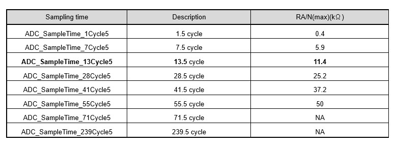
Since the output impedance of the input device is 10 kΩ, a sampling time of 13.5 cycles is specified.
And then, ADC_SoftwareStartConvCmd() is executed to start the conversion.
Execution Example of conversion start function :
ADC_SoftwareStartConvCmd(ADC1,ENABLE);//Start conversion
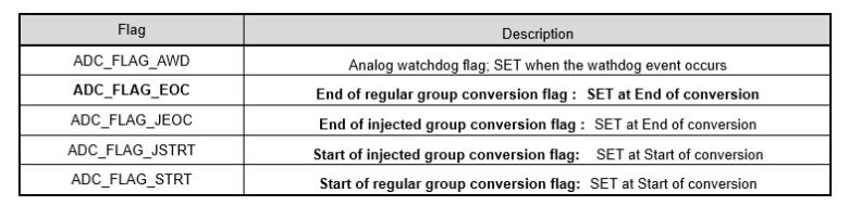
while(ADC_GetFlagStatus(ADC1,ADC_FLAG_EOC)==RESET);//Standby for conversion
ADCValue_CH1=ADC_GetConversionValue(ADC1);//Get conversion value (16 bits)
In single mode, the conversion is performed each time, so it waits for the time required for conversion before getting the conversion value. ADC_GetFlagStatus() can be used to check if the conversion has been completed. This function allows the user to check the status of the AD converter in use in terms of flags. Here, it waits until ADC_FLAG_EOC, the conversion completion notification flag, is SET (=1).
After the conversion is completed, ADC_GetConversionValue() is executed to obtain the conversion value. The function argument specifies the target AD converter (ADC1-3: depends on the MCU).
Executing these commands as a set allows AD conversion values to be obtained at any desired timing within the application program.
Continuous conversion mode
So far we have looked at setting up and acquiring conversion values in single mode. This single mode is simple and consumes less power because it is executed each time to acquire conversion values, but the conversion time is large, so it is necessary to wait until the conversion is completed.
Therefore, if you specify continuous conversion mode and execute ADC_SoftwareStartConvCmd() once to start conversion, the conversion will be repeated automatically, so you can always get the latest conversion value. To set the continuous conversion mode, simply ENABLE the ADC_ContinuousConvMode member.
Conversion on multiple channels
So far we have dealt with a single channel number. What happens to the conversion when there are multiple channels?
When converting multiple channels in single mode, the regular conversion group registration ADC_RegularChannelConfig() must be executed to specify the channels each time AD conversion starts. This is a simple method to perform a single-channel conversion for multiple channels, but it is inefficient and not practical when the number of channels is large.
Let's look at a method that performs conversion in continuous conversion mode in the case of multiple channels.
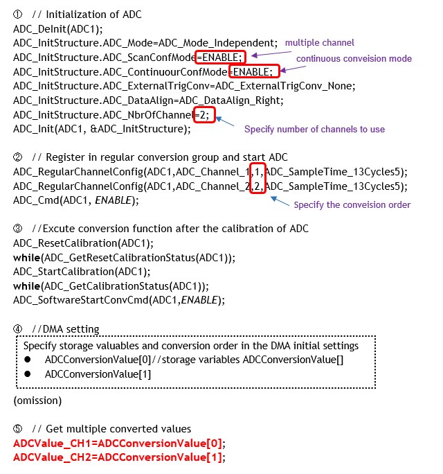
In multi-channel continuous conversion mode, the number of channels and the conversion order of channels are specified at the initial setting (1), (2), and (3).
In continuous conversion mode, the conversion value for each channel is automatically stored in a specified array variable, using a technology called DMA (Direct Memory Access).4 DMA automatically performs processing between registers and memory without CPU involvement. DMA will be explained in detail later, so it is omitted here.
In the STM32 MCU, it is essential to use the AD converter in combination with DMA for multi-channel conversion.
Sequential conversions reduce the time required for conversion, as does simplified programming.
Up to this point, we have explained the basic usage of AD converters.
In actual applications, the STM32 microcontroller can support advanced usage, such as when the number of channels is increased or when multiple AD converters are used simultaneously with low power consumption and efficiency, but the basics can be handled adequately with what has been explained so far.