Build a practical speed feedback control system for DC motor using Microcontroller
With a commercially available driver, the speed of a voltage-controlled DC motor can be easily controlled in an open loop according to the duty ratio when a PWM pulse output from MCU is given.
The speed is almost proportional to the duty ratio, but this is the case under no-load operating conditions. The limitation of open loop is that the speed is not stable when a sudden or steady load is applied.
Therefore, I improve the characteristics by providing feedback of the speed using a sensor such as an encoder to stabilize the speed even under a slight load, and also to stabilize the speed in a steady state.
Table of contents
Modeling of DC motor open loop characteristics

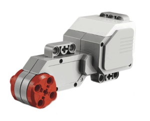
The mathematical model of the LEGO® MINDSTORMS EV3L motor with a DC motor through gears is obtained from the electric circuit and the equations of motion of the machine, and strictly speaking, the transfer function between input voltage and output speed is a second order delay system.
The original mathematical model is quite complicated because it includes modeling of the mechanical transmission mechanism, but in order to handle this motor feedback control in practice, the model must be as realistic as possible. In other words, no matter how accurate and sophisticated the mathematical model is, it will be meaningless due to actual parameter fluctuations.
Therefore, it is practical to simplify the modeling as much as possible, keeping the characteristics of the actual product in mind.
Approximate transfer function of EV3L motor
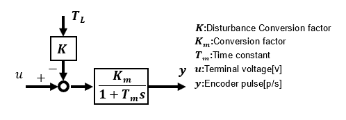
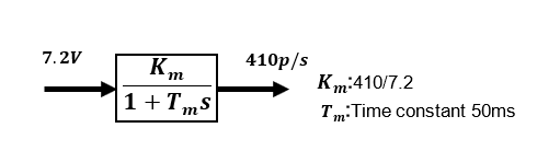
Since the transfer function can be approximated by a 1st-order lag system when the motor terminal voltage is used as input and the rotational speed of the EV3L motor as output, the time constant Tm can be identified from the change in rotational speed when the input terminal voltage is given in steps. Since the speed at the maximum voltage (7.2 V) is 410 p/s, the transfer function gain Km is also known.
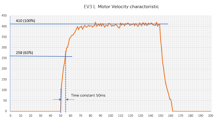
We now have an approximate model of the transfer function. The actual waveform is a 1st-order lag, so I can see that it is practical to design with an approximate model.
When a terminal voltage of 7.2[V] is applied to the input of the EV3L motor, the rotation speed on the load side through the gear starts with a time constant Tm and reaches 410[p/s] at steady state. In the actual program, the PWM duty ratio (100 in this case) is specified to provide the 7.2V command.
If the pulses from the encoder are used as a sensor for speed feedback rather than simply as a monitor, it is necessary to use a high-performance encoder with high resolution because detailed speed change data by the sensor is required.
When the encoder is mounted on the load side and the resolution is relatively coarse (180 p/r), as in this EV3L motor, an ingenuity is needed to improve the measurement accuracy. For measurement, even a simple encoder is devised to be as good as a high precision encoder.
High-gain feedback method
I will attempt to improve the characteristics using the High-gain feedback method, which is the simplest and most effective of the speed feedback methods. The high-gain feedback method consists of feedback gain C1 and output adjustment gain C2.
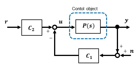
Block diagram of the High-gain feedback method. The higher the feedback gain C1 is, the better the characteristics are, hence it is called as the High-gain feedback. However, in reality, noise and other factors will be amplified, so the range in which this can be achieved is limited.
As explained in "Internal Stability" in "Fundamentals of Feedback Control using Microcontroller [Analysis]," when the feedback gain C1 is relatively small, the time constant from Noise to Output is large and the Low-pass filter characteristic is effective, however, as the feedback gain C1 becomes larger, the time constant becomes smaller(cut-off frequency is higher) and the noise tends to have a greater affect.
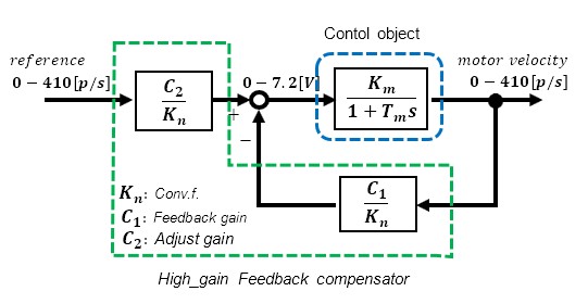
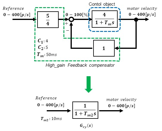
This is how the EV3L motor is applied to the High-gain feedback system. The major difference from open-loop control is that the speed target value is an input to the system and the motor rotation speed is fed back.
The area enclosed by the blue dotted line is the EV3L motor itself, the control object and the green dotted line is the controller section with High-gain feedback. This part is realized by programming.
When applying control theory to actual equipment, the important point is to always be aware of the dimensions (units) of the signals being handled. Here, a conversion factor Kn has been set to align the dimensions, but the result would be the same with or without this factor.
To simplify the program description as much as possible, the model is further approximated. In the actual program, the analog voltage value itself is not specified for the voltage command, but the PWM duty ratio (0-100). In other words, if the maximum speed pulse for 100% duty ratio at the maximum input is approximated as 400 p/s, the block diagram becomes very simple as shown below.
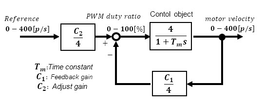
Now determine the gains C1 and C2 to determine the final characteristics between input and output after improvement. Assume that the original primary delay characteristic of the control target, Tm = 50ms, is improved to Tm2 = 10ms by applying feedback.
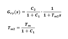
In this case, gain C1 is uniquely determined and C1=4. As a result, gain C2 = 5, which can be fine-tuned as necessary by looking at the final output.
Now the characteristic of the transfer function Gry(s) up to the output speed when the input is set to the target speed value is a 1st-order lag with time constant Tm2. Both the time constant and the effect of the disturbance are 1/5 times smaller; the characteristic can be improved by the gain of C1, but set it within the range that is feasible. The limitation of this method is that the response and disturbance suppression cannot be set independently.
For details, please refer to the comparison with the High-gain feedback method in "Fundamentals of Feedback Control using Microcontroller[Advanced]".
Actual movement
Now that I have calculated that the EV3 L motor is a 1st-order lag approximation model with a time constant of 50ms, it is time to check the operation of various control systems based on this model.
When a control system is implemented on a real machine, phenomena that did not appear in the simulation are likely to occur. This may be due to input limitations from the driver to the motor, or unexpected results due to the resolution of the sensor or processing content, etc. Therefore, it is necessary to incorporate as many conditions as possible.
Control PWM method
Because the EV3 L motor is a DC motor-based model, its speed can be adjusted simply by changing the duty ratio of the PWM pulse output, even in open control.
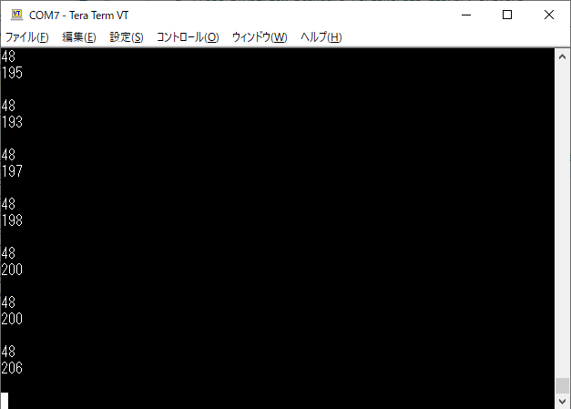
The figure below shows the pulses [p/s] from the encoder when the PWM ratio is set to 48[%]. The speed is also half of the voltage Vm (7.2V) given to the driver.
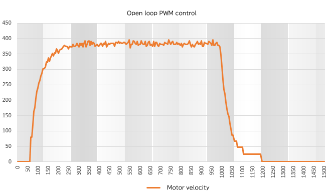
This is the response of Open-loop PWM control when a step input of 95% PWM duty ratio is given. The vertical axis is the velocity signal obtained from the encoder and the unit is [p/s]. The horizontal axis is the elapsed time, unit is [ms].
After startup, the target value is reached with the time constant Tm (50ms).
High-gain feedback method
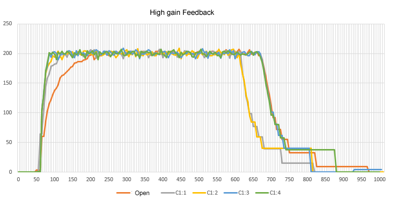
Next, the step response of the High-gain feedback method with the velocity target input set to 200[p/s] is shown. The feedback gain C1 is set from 1 to 4. Looking at the response waveforms, compared to the open-loop PWM case, the response of the High-gain feedback method improves as the time constant becomes smaller as gain C1 is increased.
The reason the response does not change even if the high gain C1 is increased above 3 is due to the motor voltage output limitation. In that sense, if a step signal with a maximum input of 400[p/s] is given, the motor will start at 100%, so changing gain C1 will not improve the response.
So far, I have verified whether the simplest and most effective High-gain feedback method for speed feedback control can be improved over the open-loop PWM control method. The EV3L motor has an encoder, but the resolution is not very high and the input is only a voltage-controlled driver PWM duty ratio, so there are some limitations in applying advanced feedback control.
In the next issue, I would like to verify what results are obtained when speed PI control and 2-degree of freedom robust control are applied under these conditions.