Encoder position measurement [STM32 Nucleo]
The STM32 timer has a function to count up and down using encoder 2-phase output pulses as input. This section explains how to use this function to measure the amount of motor rotation from the reference position by up-down counting the pulses from the rotary encoder.

With this function, for example, the pulses from an encoder directly connected to the motor shaft can be preset as the reference position at the start of measurement and then counted up and down to determine the amount the motor has rotated from the reference position.
In this application, the circuit is the same as the one used in the "Encoder Speed Measurement[STM32 Nucleo]". This time, since 2-phase pulses from the encoder output are used, CH1 and CH2 of TIM3 are used as inputs. The following is an explanation of the settings in the actual program.
Purpose: To measure the amount of rotational position by up-down counting of encoder pulses pulled up and input to CH1/CH2 of TIM3
■ Use channel CH1 (PA6)/CH2 (PA7) of timer TIM3 set as pull-up input
■ Set to Encoder interface mode to count up and down
■ Execute up-down counting after presetting the count value to the reference position with a user switch, etc.
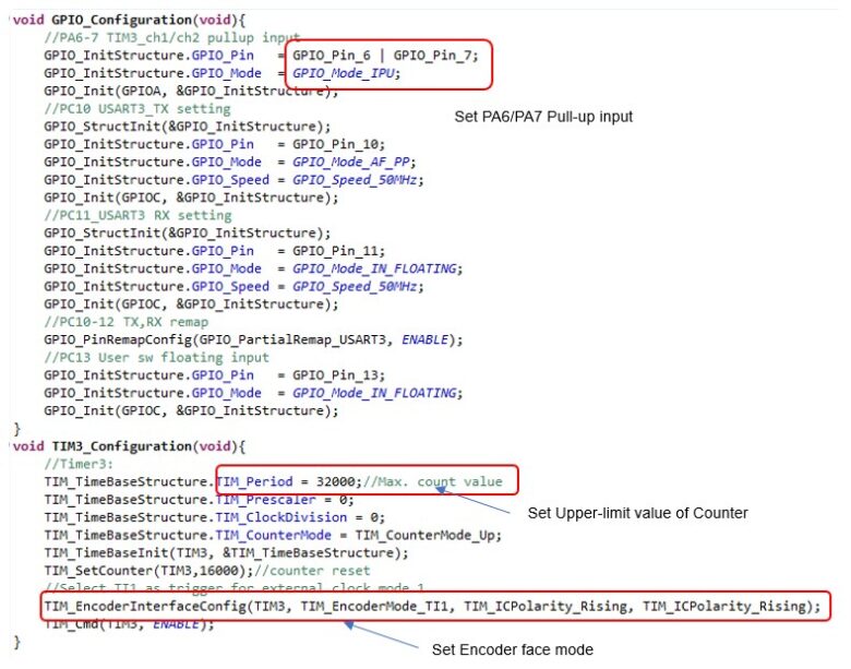
Initialization of GPIO and Timer TIM3
The initial settings of the timer are the same as those in "Encoder speed measurement [STM32 Nucleo]" so they are omitted.
Use TIM_EncoderInterfaceConfig() to set the Encoder interface mode. For details on how to use this function, please refer to "Timer Applications" in "Timer/Counter[STM32 Timers Details]".
Encoder count value acquisition and transfer to PC via serial communication
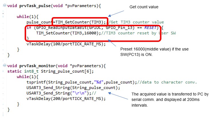
Press the user switch to preset the desired value (here based on 16000, the middle of the upper limit of 32000).
If the encoder interface mode is set to detect the edges of both CH1 and CH2, then the multiplication is 4, and for an encoder with 180p/r resolution, one rotation of the axis clockwise will increase (or decrease) by 720, and one rotation counterclockwise will increase (or decrease) by 720, and vice versa. Success is indicated by a decrease (or increase).
If either CH1 or CH2 edge is set to be detected, the value is multiplied by 2 and increased (or decreased) by 360 per revolution.
Once the rotational position of the motor is known, it is possible to realize an application in which a device that moves a motor as an actuator can move the motor by an arbitrary amount and then stop it for the next movement.
For details on the encoder counter in the STM32, see "Timer application"-"External High-speed Clock Counter" - "Encoder Interface Mode" in "Timer/Counter[STM32 Timers Details]" for a detailed explanation of the settings.