Serial communication USART [USART details of STM32]
Serial USART communication is a peripheral that can be applied to IoT in the future and should be mastered as early as possible.
USART is relatively simple to set up as a peripheral, but because it handles character strings, it requires C programming skills to master its use. This section provides step-by-step explanations from receiving a single character to DMA transfer of sending and receiving character strings.
You can also use "Serial monitor" introduced on this site as an early introduction (see "Monitor Debugging") to help improve your C programming skills.
Table of contents
What is USART?

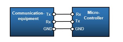
UART (Universal Asynchronous Receiver Transmitter) serial communication is an asynchronous communication method that has been used for a long time. USART (Universal Synchronous & Asynchronous Receiver Transmitter) is a method that enables synchronous communication as well as asynchronous UART communication.
This chapter describes asynchronous communication (UART) among synchronous and asynchronous serial communication USART. The asynchronous method, also called start-stop synchronous method, is a common method, but since it does not require a synchronous clock, the communication speed with the other party must be well matched.
Therefore, it is essential that the frequency of the clock supplied by the peripheral USART, i.e., the operating clock of MCU, be stable, as explained in the System Clock
For applications that use USART communication for peripherals, it is recommended to use a crystal or ceramic resonator that can supply a stable external clock for MCU operating clock. (The STM32 MCU supports full-duplex and half-duplex communication.)
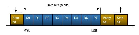
Let's look at the format for transmitting data in asynchronous mode.
Communication data (a digital value of 0 or 1) is transmitted and received in blocks surrounded by start bits and stop bits . The first bit of the block is called the start bit and is known by changing from 1 to 0. The last bit of the block is set back to 1 after transmission. This is called the stop bit.
In asynchronous communication, the start bit is used to synchronize the timing of the transmitter and receiver. The parity bit is used to increase the reliability of the communication data, and the data length is 9 bits when the parity bit is used. The parameters to be set must be the same specifications as those of the communicating party.
Initialization procedure for USART communication
This section explains the initial settings for USART communication with actual programs.
The conditions to be set are as follows
Used USART: USART3 and GPIOs are PC10/PC11
■ No hardware flow control/no parity
■ Baud rate: 9600
■ Stop bit:1
■ Data length: 8
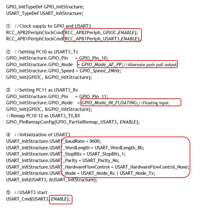
① Clock supply to USART3
Clock is supplied to USART3 used, which is connected to the APB1 bus, so it is supplied to APB1.
② GPIO setting 1 (PC10 is set to USART3_TX)
The transmit Tx for USART communication is an alternate output. The speed is matched to the baud rate.
③ GPIO setting 2 (PC11 is set to USART3_RX)
Receive Rx for USART communication is a floating input.
④ USART3 default settings
Excutes initialization of USART communication. Initialization is done by executing USART_Init() to set the above parameters.
Execution Example of USART initialization function:
USART_Init(USART3, &USART_InitStructure);
The first argument of the function specifies the USART to be set (USART1-5: depending on the microcontroller), and the second argument is a structure member, as shown below.
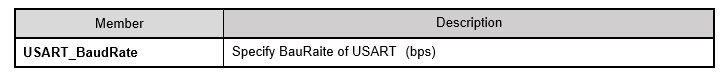
USART_BaudRate member specifies the communication speed.
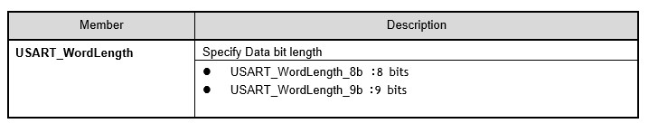
USART_WordLength member specifies the bit length of the communication data.
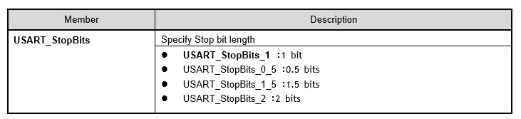
USART_StopBits member specifies the stop bits. In this example, 1 bit is specified.
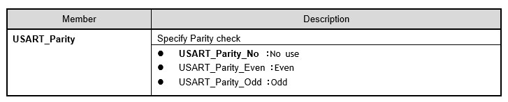
USART_Parity member specifies the stop bit. It is not used in this example.
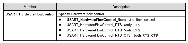
USART_HardwareFlowControl member specifies hardware flow control settings. In this example, USART_HardwareFlowControl_None is specified because it is not used.
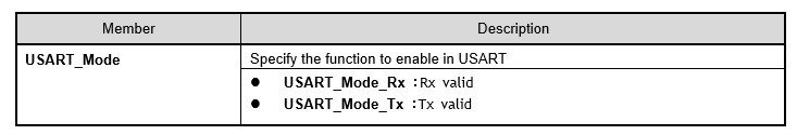
USART_Mode member specifies the function to be enabled on the target USART. Normally, both Rx and Tx are enabled.
⑤ Enable USART3
Now that USART communication has been initialized, execute USART_Cmd() to enable it.
Execution Example of USART enable function:
USART_Cmd(USART3, ENABLE);
The first argument of the function specifies the USART to be set (USART1-5: depends on the microcontroller), and the second argument is enabled with ENABLE and disabled with DISABLE.
Communication using USART
After initialization, data can be sent and received within the application program. In the case of reception, polling is used to periodically check for reception or perform reception processing only when a reception interrupt occurs.
Data received (1 character)
In communication, it would be nice if we could receive a message when the other side is about to send it, but we do not know when the other side is about to send it. Therefore, the polling method, which periodically monitors whether or not a transmission has been received and performs reception processing only when it has been received, is described here.
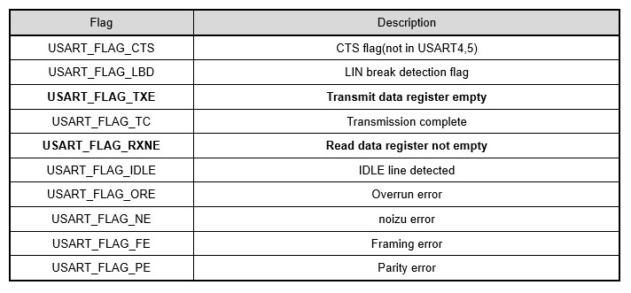
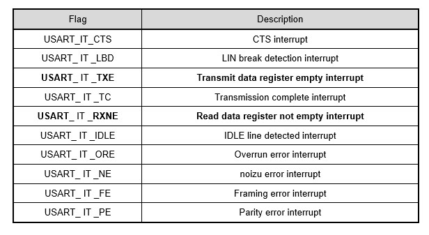
In the USART circuit, data is temporarily held in the receive register upon reception. USART_GetFlagStatus() can be used to periodically check in the application program to see if there is data in the receive register. This function can be used to check various statuses of the USART, not limited to receive, using flags. Here, when the receive data notification flag USART_FLAG_RXNE is SET (1), it can be confirmed that receive data is in the receive register.
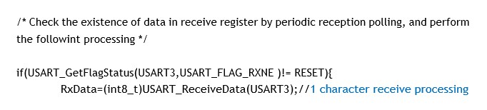
After polling reveals that there is received data in the receive register, USART_ReciveData() is executed to obtain one character of received data. This function is defined with 16 bits as the return value, but the receive data is 8 bits.
Execution Example of USART1 character receive function:
RxData=(int8_t)USART_ReceiveData(USART3);
Function prototype:uint16_t USART_ReceiveData(USART_TypeDef* USARTx)
The function argument specifies the USART (USART1-5: depends on MCU) to be set.
Data sent (1 character)
Transmission can be performed at any timing; data is automatically sent by writing one character at a time to the transmit register of the USART. When transmitting data consecutively, the next data is transmitted after confirming that the previous data has been transmitted. This can also be confirmed by using USART_GetFlagStatus() to check that the transmission has been completed and the register is empty.
When ready to send, USART_SendData() is executed to send one character of data for transmission.
Execution Example of USART1 character sending function : USART_SendData(USART3,'a');//Send 1 character'a'
The first argument of the function specifies the USART to be set (USART1-5: depends on the microcontroller), and the second argument specifies a single character to be sent.
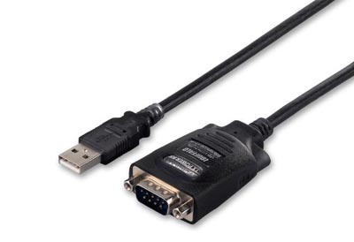
The transferred data can be transferred from MCU side to the PC side, for example, via a serial cable, and the contents can be checked by terminal software capable of serial communication. When the serial communication specifications are matched between the terminal software and the microcontroller side, the data can be sent and received.
If garbled characters appear on the display, this is due to inconsistent transfer rates.If the operating clock frequency of the microcontroller is unstable, communication problems may also occur.
In asynchronous (asynchronous) systems such as UART communication, it is a prerequisite to use a stable external clock.
Send / Receive interrupt
In the previous issue, we discussed receiving by polling. In this section, we will look at the receive processing using interrupts, where processing is performed only when there is a reception, and the transmit processing method, where interrupts are enabled only when the user wants to send a message. The settings other than interrupts are the same as for the polling method, so they are omitted.
Purpose: USART used is USART3 and GPIOs are PC10 and PC11
■ Setting of send/receive interrupts for USART3
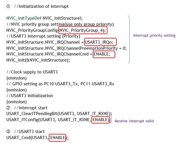
① Interrupt initialization
Interrupt initialization function Sets the interrupt priority, etc. to be used in NVIC. The NVIC_IRQChannel should be set to USART3_IRQn since this is the standard way to set up USART3 interrupts.
Set ENBLE in NVIC_IRQChannelCmd to enable the IRQ channel.
② interrupt enabled
To respond to the next interrupt with a receive interrupt, clear the status flag and then enable the interrupt with USART_ITConfig(). To clear it, use USART_ClearITPendingBit().
③ USART3 enabled
Whenever USART3 is enabled, it initiates reception by interrupt.
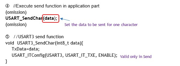
④ Execution of send function in application section
For sending, the specially created send function USART_SendChar() is executed.
⑤ Send function
The data to be sent is passed to the function before the send interrupt is enabled. If the transmit register is empty, an interrupt is generated and the USART3 interrupt handler USART3_IRQHandler is called(6).
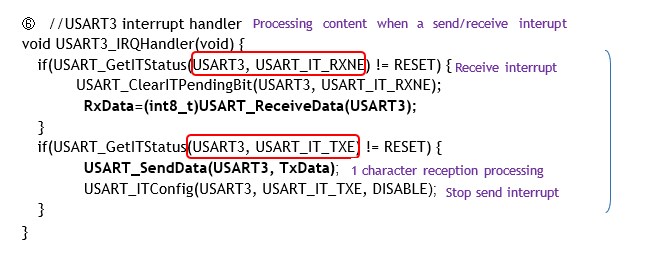
⑥ Send/Receive interrupt handler
So, the cause of the interruption, the transmitter section, is processed and the character is sent.
In the case of a send interrupt, the interrupt flag is automatically reset when sent data is written to the register. After sending, the interrupt should be stopped.
Since interrupts are used, the CPU efficiency is improved because the transmit function USART_SendChar does not have to wait until the transmit register is empty before it is executed, and the process is done automatically.
In this example, only one character is passed, but if many characters are passed as a string, the effect of sending by interruption is more effective.
String Sending and Receiving Applications
So far we have dealt with only one character for both sending and receiving. Let's develop step by step into a method for practical send/receive communication.
While sending and receiving a single character dealt with a single 8-bit variable, strings use the concept of an array or pointer. String handling requires knowledge of the C language for handling strings rather than knowledge of the microcontroller. This site does not explain the C language, but you should have a good understanding of strings, pointers, arrays, and addresses.
Applications such as telecommunications require skills to handle strings with a certain degree of freedom, in particular. If you have a good understanding of the basics and can create your own functions to handle strings, you will be able to expand the range of applications.
Let's look at an example of sending and receiving strings. Here, strings are sent and received in a polling fashion without interrupts. Functions are created for receiving and sending strings, respectively.
Since serial communication on MCU is performed in single-character units, character strings are stored in memory using arrays or pointer variables, and then transmitted and received sequentially.
These memory storage locations are referred to here as send buffer and receive buffer.
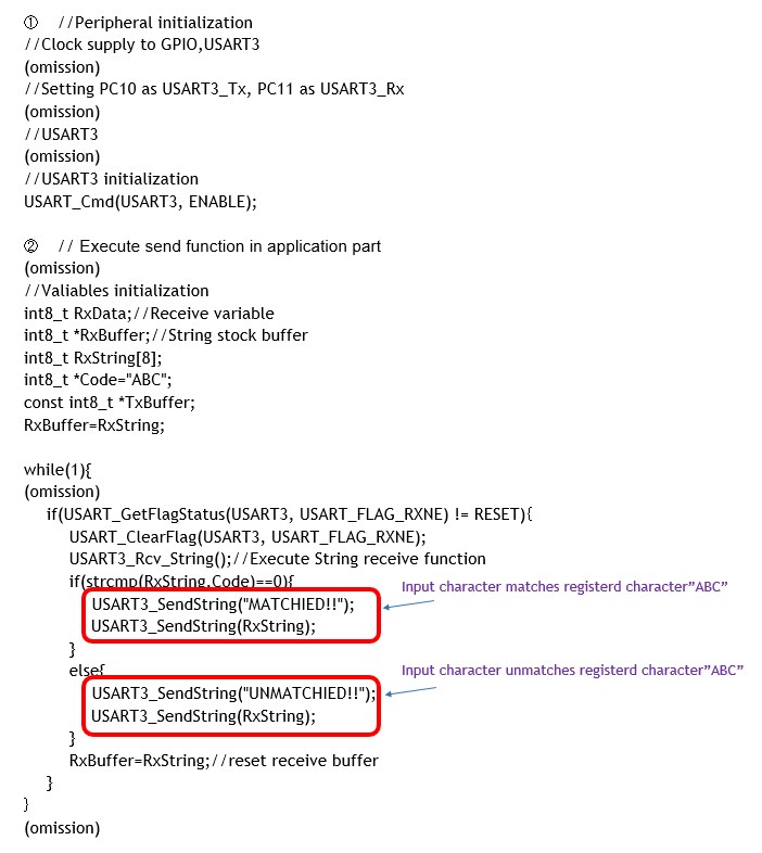
① Initialization of peripherals required for Send/Receive
Peripheral initialization has been done so far, so it is omitted here.
② Send/Receive function execution in the application section
Sending and receiving strings is described in the application.
Here, the application determines whether the string data input from the PC keyboard or other devices in the infinite loop in the main function matches the registered strings.
Receipt of a string is always monitored in an infinite loop with the receive flag USART_FLAG_RXNE, and when it changes, reception and string processing begin.
This is called the polling method, in which the CPU is constantly monitored. The receive interrupt method is used to reduce the burden on the CPU by only functioning when a reception occurs.
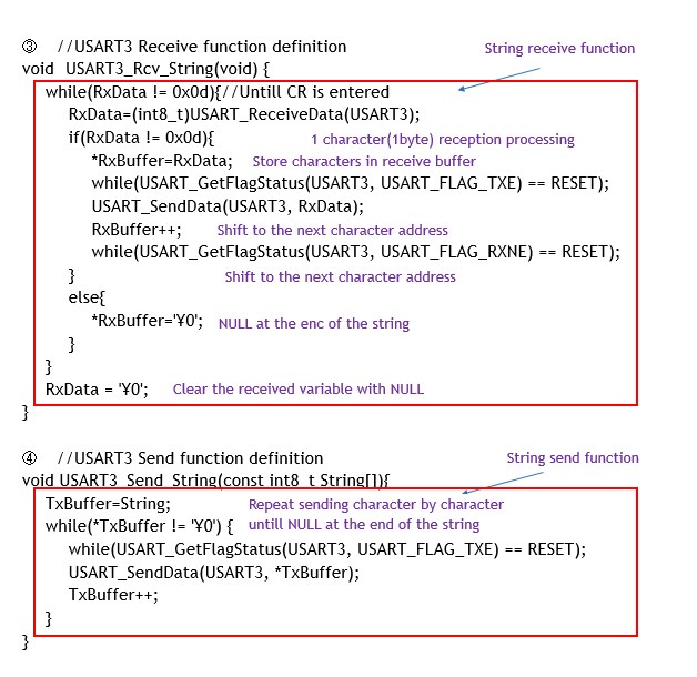
③ USART3 receive function
USART3_Rcv_string() is a function to receive strings.
Here, a character string is input by keyboard or other means, and the input character block up to the carriage return (CR) is sequentially stored in the receive buffer RxBuffer one character at a time as a character string.
④ USART3 send function
USART3_Send_string() sends a string.
Here, the string registered and stored in the transmit buffer TxBuffer is sent one character at a time until the null character is reached. Since interrupts are not used, each time a character is sent, it is necessary to wait for the flag USART_FLAG_TXE status to be checked until the send buffer is empty.
In this example, the string "ABC" is registered in a certain code, and when the code is sent from the PC side in serial communication between the PC and the microcontroller, MCU handles the case when the code matches or does not match the registered code. It can be used as a basic idea when remotely operating a microcontroller via communication from other PCs, etc. This is a good level to get used to C language arrays and pointers, so please try changing various conditions.
As with AD converters, serial communication can be made more efficient by using DMA. In other words, data can be automatically transferred to memory when sending and receiving character strings without relying on the CPU, thus reducing power consumption.
The longer the string code, the more useful DMA transfer is. For details, see "DMA (Direct Memory Access) [Details of DMA in STM32]".