Speed control of DC motors using Microcontroller PWM output [Open-loop control]
Using the L-motor of the LEGO® MINDSTORMS EV3, the STM32Nucleo board will actually operate the motor. The EV3 motor has a built-in encoder, so you can not only monitor the speed, but also get feedback for more advanced operation.
First, as a starting point for motion control using MCU, I would like to try open control using PWM signals without feedback from the encoder.
Table of contents
Motor module used in actual equipment

The open-loop characteristics of DC motors were explained in "Fundamentals of Feedback Control using Microcontroller [Application]". In this section, I will confirm speed control by voltage control using PWM output of MCU using an actual device.
The rotational speed of a DC motor can be adjusted proportionally by adjusting the terminal voltage, although with the condition that there is no load. Therefore, I will try to rotate the motor by applying a pulse voltage set by PWM to the terminal voltage.
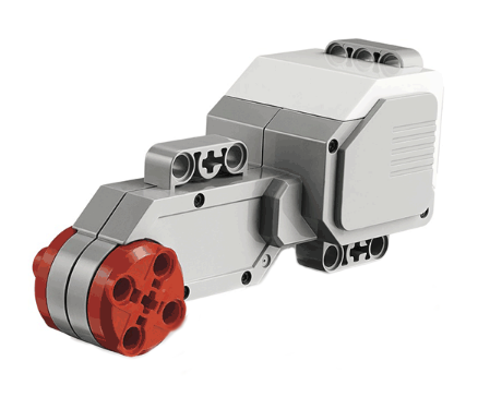
The L-motor of the LEGO® MINDSTORMS EV3 is used for the actual machine. This motor incorporates multiple gears with a gear ratio of 48:1. An encoder is mounted on the load side and outputs phase A and B pulses that are 1/4 cycle apart from each other. The actual value resolution of each phase pulse is 180 P/R. In other words, 180 pulses are output per revolution. The rated speed on the load side is 160-170 r/min.
In using this motor module, I will verify its characteristics as an integrated unit including gears, not as a single motor. That is, the input is the terminal voltage of the motor and the output is the rotational speed of the load side.
Motor Drive by MCU
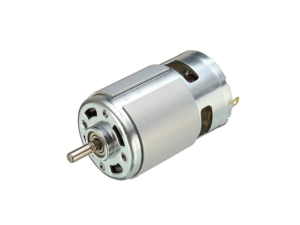
A motor is a typical inductive load that requires a lot of power and cannot be operated by directly connecting MCU output. Therefore, a separate power supply VM for motor drive is prepared from MCU power supply, and the motor is driven by the operation signal from MCU through an amplifying element such as a transistor.
Although you may configure a drive circuit by assembling transistors and other components on your own, I recommend using a dedicated IC to drive the motor for small applications. This is because the necessary functions are built in and the drive capacity is large and inexpensive for its small size.
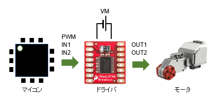
This is a kind of power amplifier called a motor driver. Without going into details, the driver has built-in power electronics circuits such as transistors and FETs that can adjust any voltage or current to the motor based on signals from the microcontroller. There are voltage-controlled and current-controlled types, depending on the type of driver. The TB6612FNG used in this project is a voltage control type.

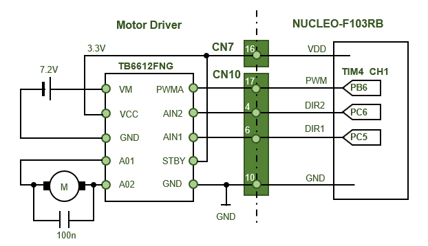
The motor driver TB6612FNG is an IC that converts the motor power supply VM connected to the driver into motor terminal voltage according to the duty ratio of PWM pulses given by MCU. The direction of motor rotation is switched by combining IN1 and IN2.
Since DC motors have built-in brushes, noise is generated between them and the commutator, which affects MCU. Therefore, a ceramic capacitor (100nF) is usually connected to the motor terminals. This is sufficient for small motors. The TB6612FNG driver module used in this project has a built-in capacitor.
PWM switching frequency of motor driver
The PWM output from MCU causes the motor terminal voltage to pulse, driving operation by drive torque during the ON period and braking operation by back EMF during the OFF period. Even though the terminal voltage is pulsed, the motor has an inductance component, so the current is a 1st-order lag of the voltage and becomes continuous.
The rate of current change depends on the electrical time constant L/R, which is determined by the inductance and resistance components of the motor. If the PWM switching frequency is low, the current will drop too much during the voltage off period (during braking operation), causing a pulsation in the generated torque even though there is motor shaft inertia.
Generally, it is said that the switching frequency should be about 10 times the motor electrical time constant. However, since the electrical time constant is unknown, I will first try a PWM switching frequency around 10 kHz.

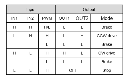
The table below describes the operation modes described in the driver specifications. The combination of inputs IN1 and IN2 is used to specify the direction of motor rotation or, in common parlance, as a function of the RUN signal. PWM is one in which the signal pattern is the motor terminal voltage; it is driven when ON, and a back EMF from the motor is generated when OFF, causing the brake to apply.
4-quadrant chopper
You may have often heard of Inverter in electric motor drive equipment. This is also a motor drive device with power electronics. Inverters are used for 3-phase induction motors and change the motor speed arbitrarily by changing the AC output frequency.
An inverter circuit is a circuit that converts a power source converted to DC by a diode bridge or smoothing capacitor in a power circuit back to AC (reverse conversion circuit), and the reverse AC to DC conversion circuit is called a converter circuit. In a broader sense of converter, there are also products called DC-DC converters for DC-to-DC voltage conversion and AC-AC converters for AC-to-AC conversion.
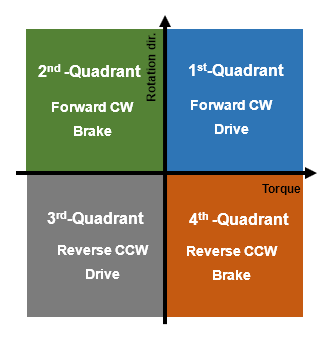
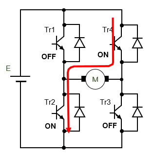
The drive circuit for a DC motor corresponds to the single-phase portion of the three-phase inverter output and is also called a 4-quadrant chopper circuit. The circuit is called a 4-quadrant circuit because it can operate the motor in four different combinations of forward and reverse rotation and positive and negative torque generation. Driving operation is normal operation in which torque is generated in the direction of rotation, and braking operation is operation in which braking is applied while torque is generated in the opposite direction of rotation, i.e., back EMF.
The TB6612FNG motor driver switches operation in the 1st through 4th quadrants by the combination of inputs IN1 and IN2 to the driver.
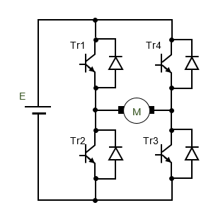
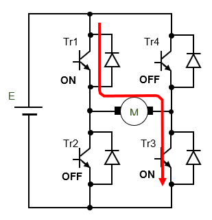
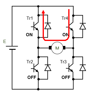
The chopper circuit consists of four transistors and other power switching elements (Tr1, Tr2, Tr3, Tr4) as shown in the figure below. These switching elements are combined by turning them ON and OFF according to the PWM pattern, and a dead time is provided to prevent the combination from overlapping and turning ON at the same time during the transient period of switching, resulting in a short circuit.
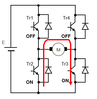
The driver TB6612FNG regenerates the power generated by the coil in braking operation by absorbing it in the circuit, while the current control type TB67H450FNG regenerates the power back to the power supply. The combination of switching elements seems to differ depending on the driver.
4-quadrant switching pattern of driver TB6612FNG
If you make your own driver, you may need to build a hardware circuit that also takes dead time into account, but the advanced-control timers (TIM1 and TIM8) of the STM32 MCU include a function to generate PWM with this dead time.
Motor drive circuit using MCU
The analog input signal from the VR (variable resistor) is given as a speed command signal. The PWM pulse duty ratio to the motor driver is programmed to change the speed in conjunction with the analog input value.
Since this is an open-loop control of a DC motor, let's check how the motor rotation speed changes by changing the PWM duty ratio, which corresponds to the speed command value.
Encoder and serial communication are for monitoring.
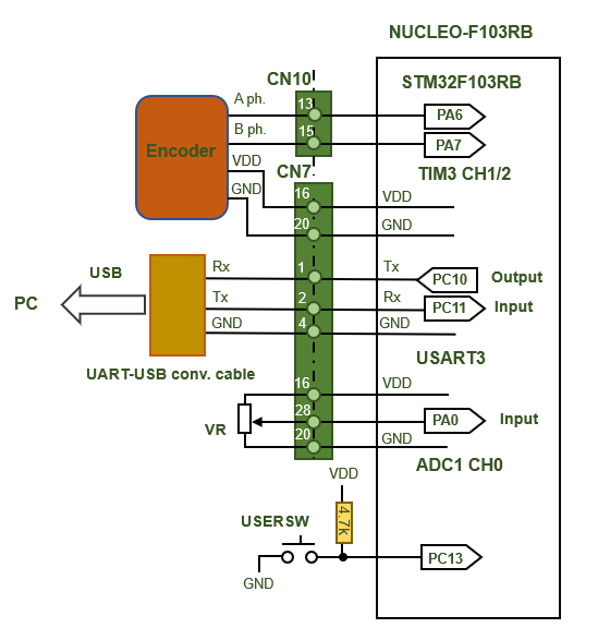
On the output side, a PWM timer output is given to the driver as a motor voltage command. The driver's IN1 and IN2 are programmed with the appropriate logic combination for the operation mode.
Each time the USER SW is pressed, the program repeats the cycle of forward rotation (CW), brake stop, reverse rotation (CCW), and brake stop.
The driver input is an internal pull-down and is designed for logic voltage input up to 6V, so the microcontroller uses a push-pull output.
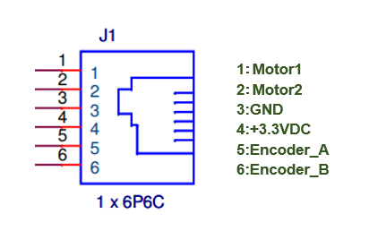
Connector specifications for EV3L motors. The encoder outputs voltage pulses.
So-called PWM-controlled motor driving uses a voltage-controlled driver, and one of the key points is how to determine the PWM switching frequency. This is related to the electrical time constant of the motor, which in this case is set at 10 kHz, but since the timer CLK is set at 1 MHz, the PWM resolution is 10 kHz/1 MHz = 1/100. In the case of a current-controlled driver, it is advantageous to apply the control theory because the current directly proportional to the torque can be made into a command value with high resolution without considering the electrical time constant of the motor.
Actual movement
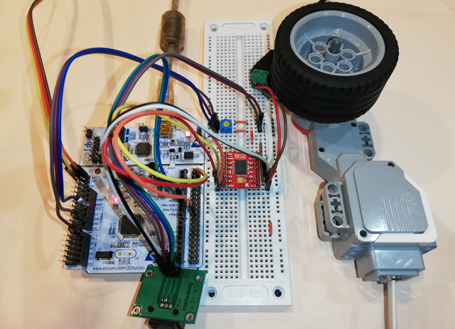
This is the full picture of the EV3L motor running on MCU board Nucleo-F103RB. The socket part of the LEGO® motor is special, so I converted it to a generic telephone modular cord.
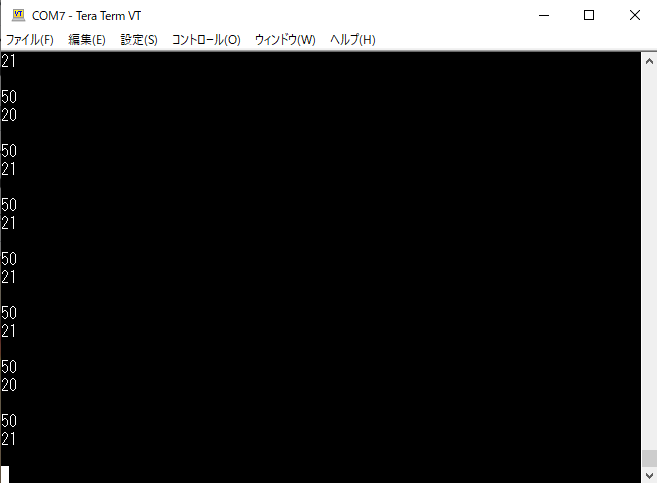
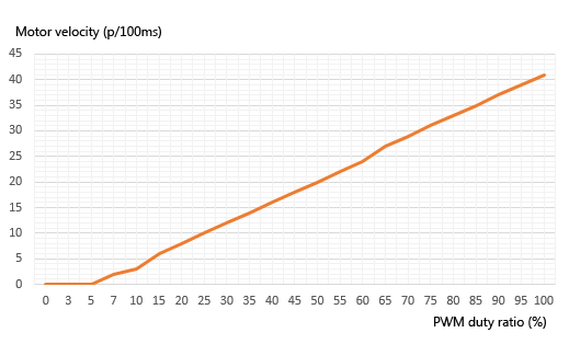
The PWM output duty ratio and the motor speed by encoder are displayed on the PC via serial communication monitor. When the motor power supply VM is 7.2V, if the PWM duty ratio is changed from 0 to 100 by adjusting the volume, the speed changes from 0 to about 40 almost in proportion to the ratio.
Speed 40 is the number of encoder pulses measured in a 100ms cycle, which corresponds to 400 pulses per second, or 400/180 revolutions per minute, or about 133 revolutions per minute. The maximum speed specified is 160-170 rpm, so setting the motor power supply VM to 9V, the maximum, will be almost the same.
This is the speed relative to the input command value during no-load operation. In the range where the terminal voltage is extremely small (duty ratio 0-5%), the motor does not start up due to friction of the motor shaft and gear, but once it starts rotating, the output speed is almost proportional to the duty ratio, or terminal voltage.
I changed the PWM switching frequency to 5kHz, 20kHz, and 40kHz to drive the motor, but there was no pulsation of torque to be concerned about and no difference in condition, so I think we should leave the frequency at 10kHz. I would like to check the current waveform when I have a chance.
Since this is an open-loop control of a DC motor, the rotational speed is proportional to the terminal voltage when no load is applied, but the speed easily fluctuates when even a small load is applied. Speed feedback control with a sensor is necessary to maintain a stable speed regardless of load. In the next issue, I would like to verify the speed control system configured with a feedback loop on an actual machine.