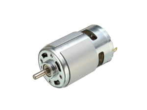
Build a robust speed control system for DC motor using Microcontroller for practical use

I will try to apply PI speed control and 2-degree of freedom robust control to a LEGO EV3L motor with an encoder attached to the load side through gears to verify their operating characteristics and effects. I would like to actively adopt these controls if they are easy to implement and effective, even for simple motors.
PI speed feedback control

PID control is the first common type of feedback control. It is often used to adjust output by sensibly setting gains without difficult theory.
This control is designed to maintain a constant target value for the originally stable EV3 motor even if conditions change slightly. In order to keep the deviation e close to zero, P (proportional) and I (integral) elements are used in the PID gain, with particular emphasis on the integral.
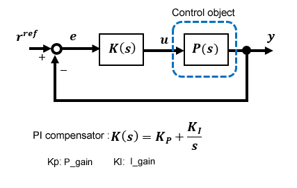
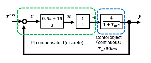
Until now, simulations to evaluate control systems have been performed using tools such as Scilab. During design evaluation, both the transfer function of the control target and the PI compensator can be s-functions of a continuous system, but in the case of actual implementation, the PI compensator must be written as a discrete system in the program.
Therefore, it is effective to use Excel simulation for evaluation to confirm the final operation close to that of the actual device. A real model such as a motor can be described by a time function of a continuous system, e.g., the 1st-order lag in step response can be described by 1-ext(-t/Tm). A compensator is a discrete system, and in an actual program, an integrator, etc. is written in consideration of the cycle period.
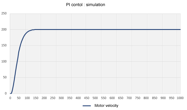
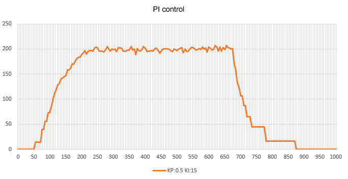
This is the response when the motor control target with 1st-order lag is a continuous system and the PI compensator is a discrete system in Excel. In order to set the cycle period to 5ms in the actual program, the simulation is a discrete system with 5ms increments.
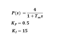
The input/output characteristics are a 2nd-order lag system because of the integral gain. If the proportional gain Kp is 0.5 and the integral gain is 15, the oscillation is suppressed, but the rise is somewhat slow because of the large integral gain. If the proportional gain is set to zero, the integral gain value may cause a slight overshoot.
At steady state, the output motor speed is stable with a steady-state deviation approaching zero thanks to the controller's integral element, but the limitation of PI control is that the response of the rising edge cannot be improved arbitrarily. PI control is sufficient for constant value control, but may be difficult to apply to tracking servo control where the input varies.
Once it is confirmed that there is no problem with the operation in Excel, all that remains is to port the same description into the program. Since the PI compensator part of the discrete system has already been written in Excel, porting is easy. The point to be noted in the actual program is the processing of initial values of variables that do not appear in the simulation. The final output to the motor is set by the PWM duty ratio.
This is the operation of the actual machine under the same conditions as the simulation. The same response characteristics as in the simulation are observed in the actual device, and the output speed is more stable than in open PWM control, with no steady-state deviation.
2-degree of freedom robust speed control
So far, I have used the PWM open control method, High-gain feedback control method, and PI control method to control the speed of DC motors, but here I would like to challenge robust control, the culmination of our efforts.
The details of the 2-degree of freedom robust control to be realized on the actual device are explained in "Fundamentals of Feedback Control using Microcontroller[Advanced]".
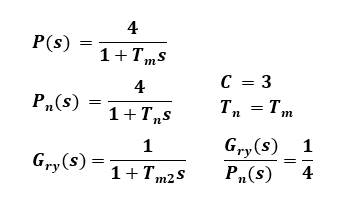
First, the parameters for applying 2-degree of freedom robust control to EV3L motors are determined while evaluating them with the simulation tool Scilab. In order to realize a 2-degree of freedom control system on an actual machine, the Pn(s) model of P(s) to be controlled must be discretized as an inverse system, which is quite complicated. Therefore, here I make a bold approximation by setting the time constant Tm2 set by the compensator to be the same as the time constant Tn of the specified model.
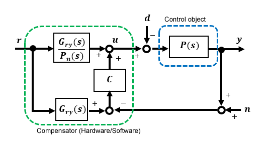
Approximation gives the block diagram of 2-degree of freedom robust control the following neat form.
If you look closely, you can see that it resembles a High-gain feedback system, the difference being that it has a 1st-order lag filter Gry(s) at the input. It is thought that the feedback section improves disturbance suppression and adjusts the response characteristics in this section.
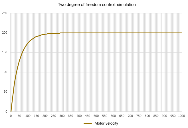
Again, as with PI control, I first simulate and evaluate the results in Excel. The control target surrounded by the blue dotted line is described as a continuous system, and the robust compensator surrounded by the green dotted line is described as a discrete system.
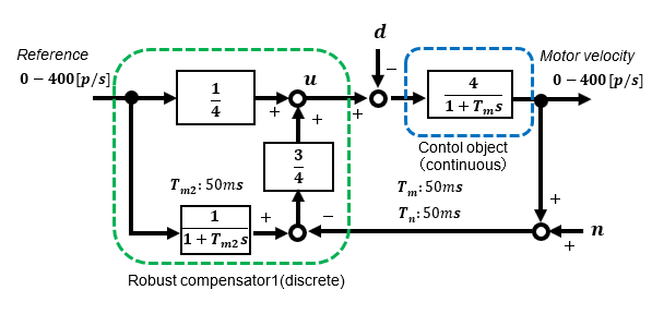
For disturbance suppression, a larger feedback gain C is more effective. In the simulation, the startup is performed with a set primary delay system time constant of 50ms.
This is the response of 2-degree of freedom robust control on a real machine. The time constant Tm2 is set to 50ms for this approximate system, but when we tried setting the time constant Tm2 to a different value, we found some differences in the rise time depending on the time constant even in the approximate model. Although not shown here, the output speed is very stable even when a disturbance load is applied.
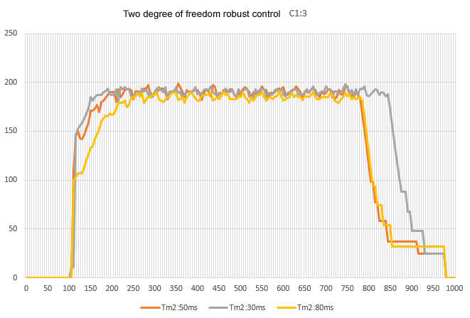
Since the features of so-called robust control are well represented and relatively easy to implement, I think it can be actively utilized in small applications.
So far, I have verified speed feedback control with a constant value control step response. In the next issue, I would like to compare and verify the speed servo control that follows the input with each control method, since trapezoidal wave patterns are often given as practical speed inputs.
To simplify 2-degree of freedom robust control, the time constant of the 1st-order lag filter Gry(s), which determines the target value response characteristics, is the same as that of the nominal model.
However, the step response in constant value control can be improved to some extent even under these approximated conditions. In servo tracking control such as ramp response, the performance of the simplified approximation is limited, so it is more reliable to configure the original control compensator in the program.
However, since floating-point arithmetic is required to achieve this, the simple approximation type may be sufficient for applications with relatively slow operation.