Build a speed servo control system for DC motor using Microcontroller for practical use

So far, I have checked the characteristics of each of the LEGO EV3 motor using DC motor with step response (constant value input) of various control methods. In actual operation, the motor is not only used at a constant speed, but is also used in many applications for so-called servo operation, in which acceleration and deceleration follow an arbitrarily given pattern.
Therefore, this time, for each control method, when a trapezoidal speed pattern created in advance is used as the command value input, I will check the tracking performance when a load is manually applied and the effect of fluctuations due to external disturbances.
First, I would like to confirm each control method by simulation, then apply the program to the actual machine to check the differences in characteristics between the control methods and explore more practical methods.
Both the simulation and the operation check on the actual machine will be studied with the same device as has been explained in the step response so far, with a trapezoidal velocity input command.
Strictly speaking, a servo is designed to achieve zero deviation of output from a target value, but here I refer to a servo in the broad sense of tracking an arbitrary input value.
Table of contents
Speed servo control with open control

In the case of open control, to make the speed command value a trapezoidal pattern, specify a PWM duty ratio such that the voltage is proportional to that command value.
The motor speed should run in proportion to the voltage given at no load.
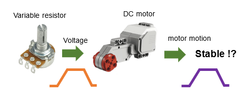
Assuming a load that could occur in actual operation, a constant load torque is applied to the motor shaft at intervals of about 0.5s in the direction of the brake, and the effect on the motor speed at output is verified.
As explained in "the Basic Knowledge for Feedback Control Realized with Microcontrollers [Application]", DC motors are greatly affected when a load is applied to them in open control.
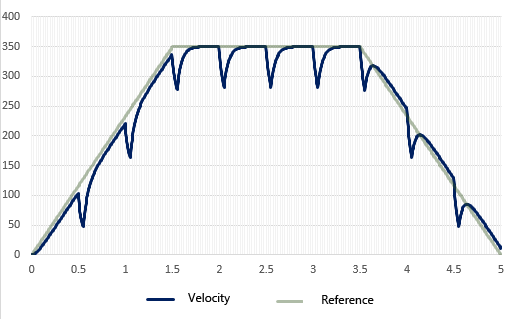
If we first check the simulation, we see that the speed of output can still vary considerably, as the theory proves.
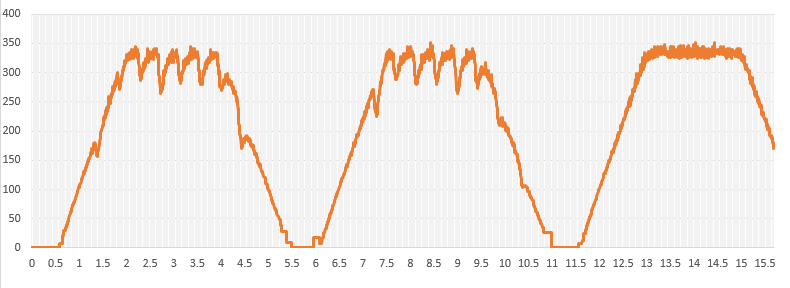
Now, create a program that will have the same conditions as the simulation, and measure the actual speed when the motor is given a voltage that causes the speed command value to be a trapezoidal pattern.
The same results as in the simulation confirm that the speed fluctuates immediately with a slight load.
If this unprotected condition is applied to the drive of a Micro-mouse, for example, it is possible that even obstacles such as a gradient or a slight step may prevent the desired movement.
Therefore, we will check the tracking performance against the speed command value (reference value) and the affect of external disturbances using various methods with motor speed feedback to further improve the performance.
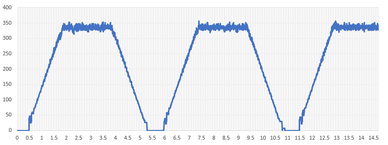
The speed command pattern is a trapezoidal pattern with an acceleration/deceleration time of 1.5 s and a steady-state speed time of 2 s. The calculated data for each control cycle time (5ms in this case) is included in the array. The rated speed of the motor used (when 7.2V is applied) is 410p/s, so the speed peak of the command value is set slightly lower at 350p/s to give more leeway.
Speed servo with PI control
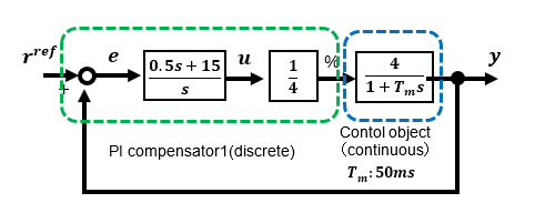
Among the PID controls, a feedback speed control with proportional and integral elements as compensators is configured to check its performance.
This is a trapezoidal pattern of speed command values under the same conditions as for the step response. The compensator is set to a proportional gain of 0.5 and an integral gain of 15.
First, simulations show that under these conditions, the affect of disturbance is the same as in open control, with almost no improvement.
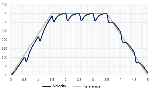
The results of actual measurement under exactly the same conditions as in the simulation are similar, but the difference from open control is that there is no longer a steady deviation between the speed command value and the actual speed.
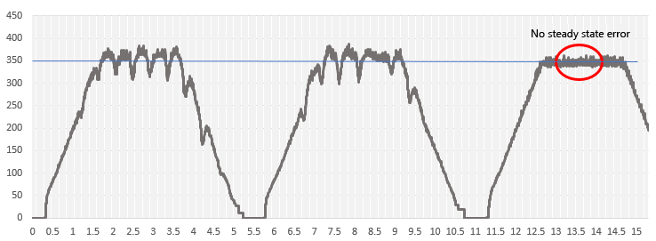
In the present conditions, the gain was set relatively small, and therefore, it can be said that the effect of suppressing the affects of disturbances is negligible. However, a larger gain setting can suppress the affect of external disturbances, but a larger gain for the entire loop is not desirable because the loop is more susceptible to noise and other influences.
It can be seen that PI control is an effective method for eliminating steady-state deviations, but it is not very effective for eliminating the affects of disturbance loads.
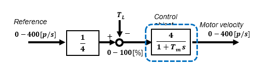
Speed servo with high-gain feedback control
This time, let's verify the simplest feedback method, the High-gain feedback method, which is easy to make effective.
Although I call this method "High-gain feedback", it is actually a very practical method that does not use very high gain.
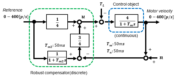
The conditions to be verified are shown in the block diagram below.
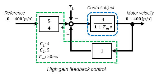
Under the above conditions, the characteristic between input and output is effectively a 1st-order lag system with a time constant of 10ms. For details, see "Build a practical speed feedback control system for DC motor using Microcontroller".
First, the simulation confirms that the load disturbance that had affected the open speed control and PI speed control is almost canceled by this method, even though the conditions are the same, and the servo operation tracks the speed command value.
The simulation was a good result, but what about the actual measurements?
I configured the program under the same conditions as in the simulation and made actual measurements. Programming the control algorithm is simpler than PI control, which uses an integrator.
Here again, as in the simulation, the result cancels the affect of disturbance and stably follows the command value.
Speed servo with 2-degree of freedom robust control
The High-gain feedback method was a simple yet highly effective method, but its disadvantage was that it increased responsiveness at the same time as the gain was increased to enhance disturbance suppression.
This is fine if there are no problems, but if you want to set disturbance suppression and responsiveness independently, an effective method is the two-degree of freedom robust control method.
In this case also, the only difference is that the speed command value (target value) is made into a trapezoidal pattern to the one configured with a step response. The approximate type is easy to configure for simulation and programming. See "Build a robust speed control system for DC motor using Microcontroller for practical use".
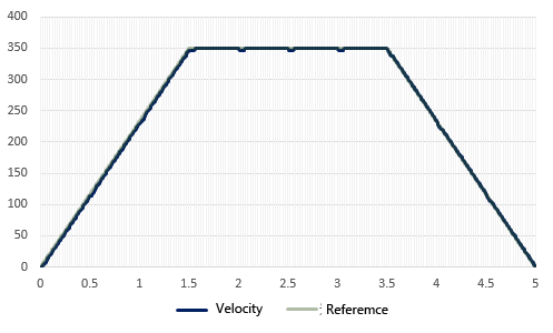
First, the simulation confirms that, compared to the High-gain feedback method, the speed lags slightly behind the command value because the time constant Tm2 of the robust compensator is set to 50ms, the same as the time constant Tm of the motor control target, for the approximation type.
It was confirmed that the disturbance suppression is effective enough as well as the High-gain feedback method.
Programming the control algorithm requires configuring a filter with a 1st-order lag, but it is not that complicated.
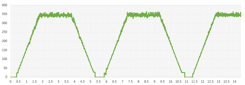
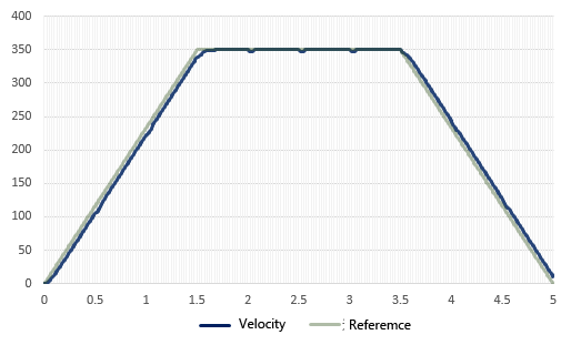
It can be verified that the measured values follow the command value stably without influence of disturbance even under the same conditions as in the simulation. It was confirmed that the approximate type is effective enough.
Summary
- Open control allows simple speed adjustment, but it is not suitable for speed servo-like operation at arbitrary speeds because it is easily affected by external disturbances.
- Even if a DC motor is operated by PI speed control, it will be affected by external disturbances. PI speed control is suitable for applications where the motor is operated according to a constant speed command value (target value) with a constant load applied, but is difficult to apply to speed servo operation where the target value varies. A high gain must be used.
- The High-gain feedback method is recommended as it is relatively easy to cancel the affects of disturbances. Care should be taken not to make the response too high depending on the gain value.
- Two-degree of freedom robust control is effective when you want to improve disturbance suppression while also adjusting responsiveness as desired. The approximate type is sufficient for this purpose, but the original type is more effective if you want to set up a more serious configuration. However, the control algorithm in the program becomes more complicated due to the increase in the order of the control compensator.
In conclusion, the High-gain feedback method is practical and recommended for small applications with disturbance suppression, including 2-degree of freedom robust control, although steady-state deviation remains as it is, it is easy to make it fully servo. I will introduce it soon.
The High-gain feedback control method and 2-degree of freedom robust control method (approximate type) are very practical methods that can be programmed with only a few lines of description. They can be easily adopted even for a hobbyist application.