Various interrupts [Interrupt details in STM32]

Interrupt processing is unavoidable in embedded programming that controls hardware. Interrupt processing in the STM32 MCU is based on the rules of the ARM Core Cortex-M3, so it is necessary to understand how the rules work and to write the interrupt processing settings and processing details. This chapter explains the interrupts specific to the ARM Core Cortex-M3 using example programs.
Table of contents
What is interruption?

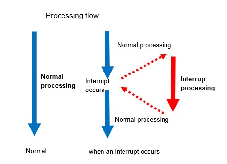
Interrupts were introduced in the System Clock Timer chapter, and this chapter describes the interrupts handled by the STM32 MCU. Interrupt is to suspend the running program and perform a specific process.
Interrupt functions are provided for timers, AD converters, UART serial communication, and other peripherals, so that when used in combination, the burden on the CPU can be reduced and an efficient system can be built.
In this section, I will use the interrupt function provided by the timer in the previous chapter to explain the process.
Interrupt handling settings
In the previous section, the timer was used in output compare mode to operate the GPIO output port by comparing the input clock count with the value set in the capture compare register (CCR). Here I will look at the case of using capture compare interrupts.
In order to use interrupts, it is common to use any peripheral, but in addition to setting each peripheral
(1) Interrupt initialization
(2) Enable interrupts
(3) Create interrupt handler function describing the process are required.
Now let me explain the settings in the program.
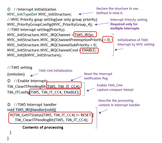
① Interrupt initialization:
Peripheral (peripheral function) interrupts are managed by NVIC (Nested Vectord Interrupt Contoller) in ARM core MCUs. NVIC is a nested vector interrupt controller. Nested (multiple) means that when multiple interrupts are generated, they are processed in order of priority.
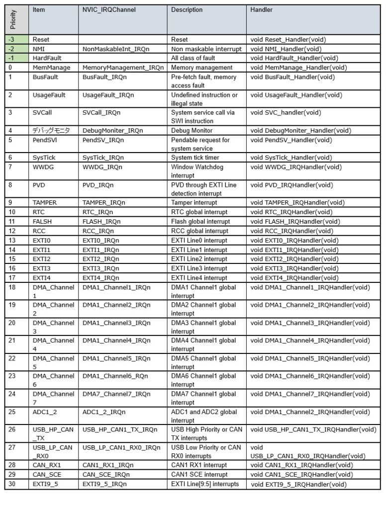
Vectors are unique numbers that indicate interrupt factors, and when an interrupt occurs, they are grouped in a corresponding table called a vector table that defines processing items according to the interrupt factors. Interrupt vectors indicate the type of interrupt that has occurred.
In ARM Cortex-M3 core MCUs, the NVIC manages all peripheral interrupts, so interrupt initialization is done by NVIC settings.
The NVIC is the part that configures how interrupts generated by each peripheral are handled and in which priority order.
NVIC is configured with NVIC_Init(). There are four types of parameters to be specified as members of a structure variable.
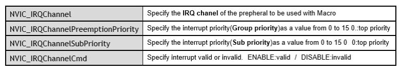
The NVIC_IRQChannel is set to the type of interrupt to be used and is selected from the NVIC_IRQChannel list. These are macros defined in the library stm32f10x.h. For example, TIM5_IRQn (TIM5 global interrupt) is equivalent to TIM5's CH4 capture compare interrupt.
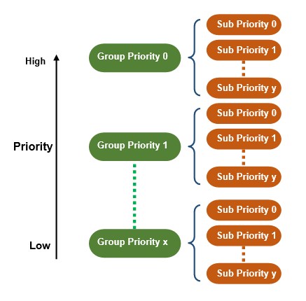
The group priority determines which interrupt is processed first when multiple interrupts are occurred. 0 to 15 can be specified for NVIC_IRQChannelPreemptionPriority; the smaller the number, the higher the priority. 0 is the highest priority.
For example, if interrupt process B with group priority 0 occurs while interrupt process A with group priority 1 is being executed, process A is interrupted and moved to process B. Also, if interrupt process A with group priority 1 occurs while interrupt process B with group priority 0 is being executed, interrupt process B will continue. If interrupt process C with the same group priority occurs while interrupt process A is being executed, interrupt process A continues and moves to process C after completion.
When multiple interrupts with the same group priority occur at the same time and are waiting to be executed, the sub-priority determines which interrupt to process first. NVIC_IRQChannelSubPriority can be specified from 0 to 15, the lower the number, the higher the priority. 0 is the highest priority.
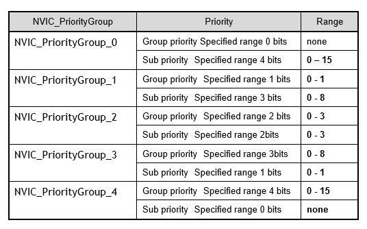
Priority can be assigned in 16 ways (0 - 15) for 4 bits, but in STM32, group priority and sub-priority assignments are specified in combination, and each can be assigned in 16 ways from 0 to 15, rather than 4 bits for group priority and sub-priority together, or 16 ways.
This priority assignment method is specified in NVIC_IRQChannelPreemptionPriority().
If this function is not specified, only the group priority is valid, as when NVIC_PriorityGroup_4 is specified.
Execution example of NVIC_IRQChannelPreemptionPriority():
NVIC_IRQChannelPreemptionPriority(NVIC_PriorityGroup_4);
The interrupt priority setting is used when multiple interrupts occur simultaneously, but for relatively simple interrupts, only a group priority setting (NVIC_PriorityGroup_4) is sufficient.
② Enabling Interrupt:
After the NVIC has been configured in the interrupt initialization, each peripheral is configured to generate an interrupt to notify the NVIC what kind of interrupt has occurred. The timer interrupt example uses TIM_ITConfig().
Execution of Example of TIM_ITConfig():
TIM_ITConfig (TIM5, TIM_IT_CC4, ENABLE);
The first argument of the function specifies the timer to be set.
■ Timer to be set : TIM1 – TIM8
The second argument specifies one of the following macros for the interrupt to be enabled.
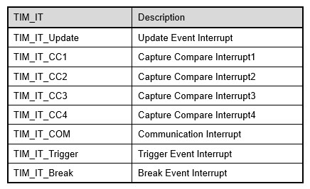
The third argument specifies whether it is enabled or disabled.
■ ENABLE
■ DISABLE
Peripheral interrupts are now enabled.
③ Create interrupt handler functions:
When an interrupt occurs, the target interrupt handler function is called and the processing in the function is executed.
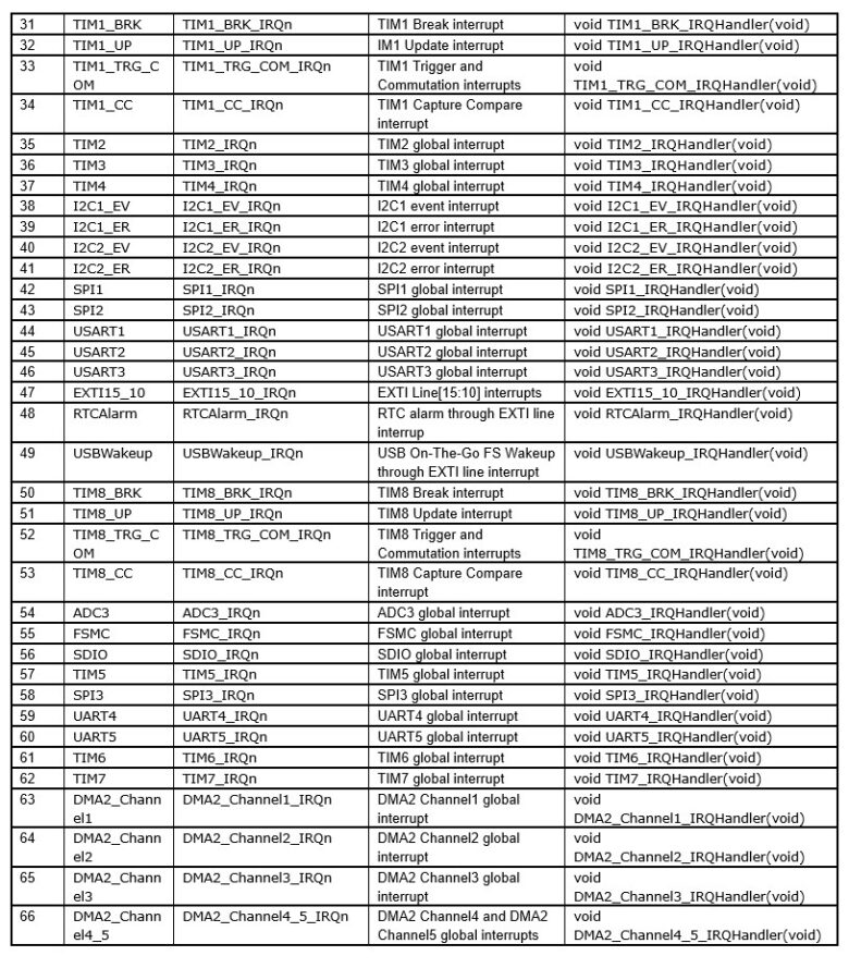
The handler function names are defined in the NVIC_IRQChannel table, so please refer to this table. In this example, TIM5_IRQHandler() is used.
In the case of TIM5, the interrupt handler function TIM5_IRQHandler() is called whenever an interrupt occurs, but there are several types of interrupt contents and it is not known which interrupt occurred.
Check the interrupt status flag to see if the target interrupt has occurred, and then move on to execute interrupt processing if necessary. TIM_GetITStatus() is used to check the cause of the interrupt.
Execution example of Interrupt Status:
if(TIM_GetITStatus(TIM5, TIM_IT_CC4) != RESET){
TIM_ClearITPendingBit(TIM5, TIM_IT_CC4);
[interrupt contents]
}
The first and second arguments of the function are the same as for TIM_ITConfit(). This function has a return value indicating the status flag, and
■ SET : Interruptions are occurring.
■ RESET : No interruptions have occurred.
In the above example, if the status flag is not RESET, the CH4 capture compare interrupt of TIM5 has occurred, and the flow is to execute processing at the time of the interrupt.
The interrupt status flag is not automatically cleared (reset) after interrupt processing is completed. Therefore, it must be manually cleared in order to respond to the next interrupt. To clear the interrupt status flag, use TIM_ClearITPendingBit().
Execute Example of interrupt status flag clearing function : TIM_ClearITPendingBit(TIM5, TIM_IT_CC4); : TIM_ClearITPendingBit(TIM5, TIM_IT_CC4);
The first and second arguments of this function are also the same as for TIM_ITConfit().
The interrupt status flag clearing function should be executed just before the interrupt handler is called and the interrupt processing is executed to clear the flag. It should also be reset immediately before activating the interrupt.
Now that the preparations for using interrupts are complete, all that remains is to describe the processing to be performed when interrupts are used. Usually, it is better to use only simple processing instead of complex processing. This is because interrupts interrupt other processes.
For example, if an interrupt is occured when serial communication is received, instead of executing the entire reception process in the interrupt process, the reception notification flag (1 when reception occurs, 0 otherwise) is simply set and the process itself is executed in the main program according to the flag status, eliminating the burden of interrupt processing.
Interrupt by external input
So far, I have introduced an example of interrupt operation with the general-purpose timer TIM5. Next, I introduce interrupts by external input.
External input interrupt
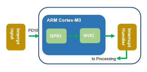
In applications that use PD10 input as an interrupt, when a signal is received at input port PD10, normal processing is interrupted and the process moves to the interrupt handler EXTxxxx_IRQHandler().
The process to be executed when an interrupt occurs is described in this function. The program flow using interrupts is as described in the section on each peripheral function - Various Interrupts. The only difference is that instead of using the interrupt function of each peripheral, an external input signal is used to trigger an interrupt.
Although omitted in the example below, the clock is also supplied to the GPIO used for the interrupt signal pin, and the pin is set to input. (PD_10)
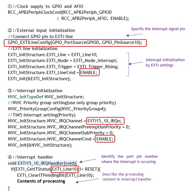
① AFIO clock supply:
AFIO clock must be supplied when using EXTI.
② External input initialization:
First, run GPIO_EXTILineConfig() to connect the specified GPIO port to the EXTI line. The first argument of the function specifies port x (A to G) (GPIO_PortSourceGPIOx), and the second argument specifies pin number y (0 to 15) (GPIO_PinSourcey).
Execution Example of GPIO_EXTILineConfig()(PD10) :
GPIO_EXTILineConfig(GPIO_PortSourceGPIOD, GPIO_PinSource10);
Initialization is performed by executing EXT_Init(). The arguments of the function are structure members and contain the configuration parameters shown below.
Example Execution of EXTI initialization for external input interrupt: EXTI_Init(&EXTI_InitStructure);
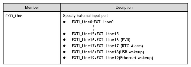
EXTI_Line member specifies the input port to be used for interrupts; there are 20 EXTI lines, and 16 lines up to pin x (0-15) specify EXTI_Linex, which corresponds to the pin number. The other four EXTI lines 16-19 are used for wake-up by event lines.
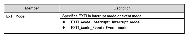
EXTI_Mode member specifies whether EXTI is used in interrupt mode or event mode.
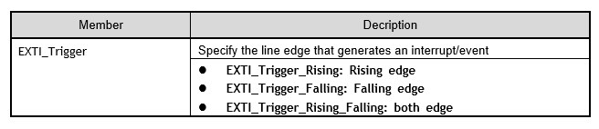
EXTI_Trigger member specifies the line edge that generates an interrupt or event.
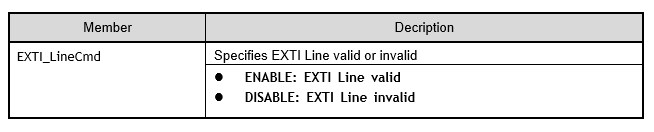
The EXTI_LineCmd member enables or disables the EXTI line.
③ Interrupt initialization:
For external input interrupts, specify the IRQ channel corresponding to the pin number in the structure variable member NVIC_IRQChannel. For pin 10, this is EXTI15_10_IRQn. Other settings are the same as for other interrupts.
④ Describe the process in the interrupt handler:
Describe what you want to process in the function (interrupt handler) called by the interrupt.
The specific handler to be called is invoked by the interrupt line. As described in the Interrupt NVIC_IRQChannel list.
The interrupt handlers EXTI0_IRQHandler() through EXTI4_IRQHandler() are called independently for pins 0 through 4, but EXTI9_5_IRQHandler() is called for pins 5 through 9 and EXTI15_10 _IRQHander() is called for pins 10 through 15. Therefore, pins 5 through 15 must be checked with EXTI_GetITStatus(EXTI_Linex) pin number x(5-15) to identify which pin the interrupt is from in the called interrupt handler.
Since the flag must be cleared for each interrupt, EXTI_ClearITPendingBit() is used.
Execution Example of Interrupt Status Flag Clearing Function : EXTI_ClearITPendingBit(EXTI_Line10);
The arguments of this function are also the same as those of the EXTI_GetITStatus function.
Other interrupts include AD converters and UART serial communication. Although the function names and argument names in the peripheral library are different, the flow of usage is almost the same as for timers. I will introduce the actual usage of interrupts in the Application and Practical Chapters.
Interrupt NVIC_IRQChannel List