Power Supply without Failure for Embedded MCU system [ARM Core STM32]
When running applications on a MCU, a very important thing is to provide a stable power supply. This may seem obvious, but the power supply is so profound that a serious study of it would end with this part alone. It is important to understand the basics to prevent problems caused by unstable supply voltage, insufficient power supply capacity, and external noise through the power supply.
Power supplies are composed of highly designed devices and components called regulators, which are the culmination of analog technology, and we, MCU users, select appropriately from a wide variety of devices and components to build a power supply peripheral circuit suitable for MCU we use.
This time, although not limited to the STM32 MCU, I would like to explain how to configure the power supply peripheral circuits suitable for the MCU based on the author's experience in order to supply a stable power supply voltage, while also introducing components used in the periphery.
Table of contents
Power supply configuration required for MCU operation

MCUs may be powered by batteries, but here I will discuss supplying power voltage from an AC power supply.
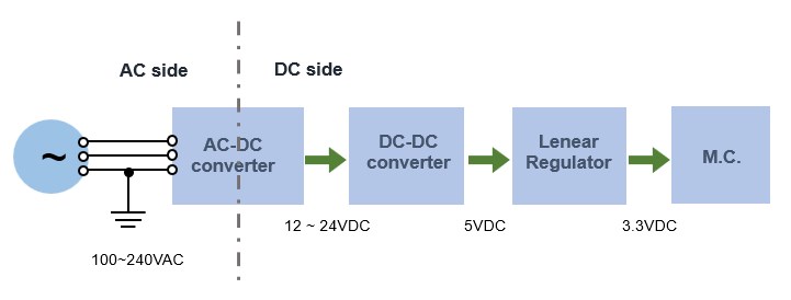
We will look at a configuration for supplying DC 3.3V, which is the standard MCU power supply voltage. Some MCUs can operate at around 1.5VDC, equivalent to one dry cell battery, for portable devices such as smartphones.
In Japan, the general power supply is 100 VAC AC, so a device (AC-DC converter) that lowers the voltage of 100 VAC and converts it to DC is required first. AC-DC converters are mainly of the switching regulator type, which drastically reduces the input voltage and converts it from AC to DC at the same time. The AC adapters that come with home appliances also fall under this category.
When only a MCU is used, a switching regulator may be used to drop the voltage directly to a level close to MCU power supply voltage to create, for example, 5 VDC, but here I will create an intermediate power supply of 12 VDC or 24 VDC, considering the case where a voltage higher than MCU power supply voltage is required, such as in power supplies for commercially available sensors.
Next, a DC-DC converter is used to drop the intermediate 12 VDC or 24 VDC power supply close to MCU power supply. The principle of this DC-DC converter is the same as that of a switching regulator, and it seems to be possible to directly create a DC3.3 MCU power supply, but considering the noise generated by a switching regulator, we will use a component called a linear regulator with one more stage added.
About AC-DC converters (power supply)
A electrical circuit that takes an AC power source as input, rectifies it with a diode, and then controls it to a stable and specified DC voltage is called a power supply (regulated power supply circuit), and there are various types of power supply systems. The simplest power supply circuits are those that create a certain level of DC voltage with transformers, rectifiers, and smoothing capacitors, etc., although they cannot be called stabilized. Stabilized power supplies include series regulator (linear regulator) systems and switching regulator systems that use semiconductor devices to control output voltage.
The power supplies used in MCUs are mainly of the switching regulator type, which are lightweight and compact, but we would like to introduce the linear regulator type as well for reference and discuss the advantages and disadvantages of each.
Non-switching regulator method
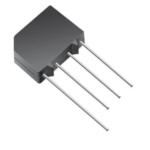
There are a method that combines a half-wave or full-wave rectifier circuit with a diode and a smoothing capacitor, and a series regulator method that controls the load voltage with a transistor or other element in series with the load. All of these methods have in common the step-down of the AC input power supply via a transformer followed by rectification by a diode bridge.
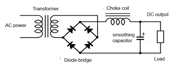
Power supply with smooth capacitors and choke coils
This is the simplest DC power supply. Even if the output voltage is equalized with a choke coil and smoothing capacitor, some ripple remains.
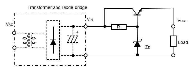
DC power supply with transformer and diode
The aforementioned circuit is controlled by a feedback element to ensure that the load voltage is always constant. This method of DC stabilized power supply is very stable and has the advantage of not generating noise. However, since a transformer is used, the voltage drop is a loss and the size of the power supply is rather large.
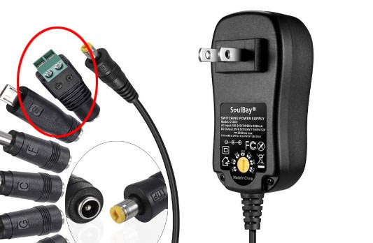
Switching regulator method
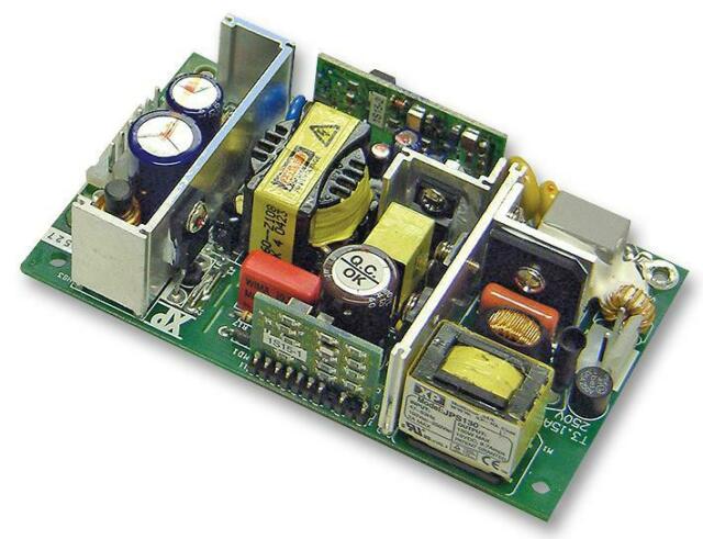
Commonly referred to as switching regulators, switching power supplies, or AC adapters, these devices are now so commonplace that they are rarely seen in the home. Molded resin devices have relatively small capacitance and can be found in home appliances, while devices for industrial equipment have larger capacitance and metal frames that allow for heat dissipation.
This switching power supply uses a commercial power source as input and controls the average voltage using a semiconductor switching element on the principle of pulse width modulation (PWM), so to speak. Therefore, while a transformer is used to step down the voltage in the linear regulator method, the switching method can step down the voltage without using a transformer. The greatest feature of the switching method is that it generates less heat and has higher efficiency than the linear regulator method.
On the other hand, since the high-speed switching operation generates harmonic noise, which appears as ripple in the output voltage and adversely affects the input side, it should be used with the understanding that solid noise suppression measures may be necessary.
The key to selecting a switching power supply, not only a MCU, is to calculate how much maximum capacity (current) is required on the load side, and select a larger one that will not be insufficient.
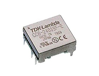
About DC-DC Converters
A DC-DC converter is used to reduce the DC voltage to a level close to MCU power supply. The DC-DC converter is a switching type that converts DC to DC, and is available not only as a step-down converter but also as a step-up converter. If the voltage difference to be converted is not too large, a component called a linear regulator (three-terminal regulator), which is explained next, is inexpensive and easy to use. However, if the voltage difference is large, it is safe to use a DC-DC converter considering the heat generated by the maximum current available in the load.
DC-DC converters are available from a variety of manufacturers, some with electrically isolated inputs and outputs, and some with a pin layout compatible with linear regulators.
The former isolated DC-DC converter electrically isolates the input side from the output side to ensure safety and provide noise suppression. The latter type of DC-DC converter is compatible with linear regulators and can easily replace them if there are concerns about heat generation. It is convenient to use a DC-DC converter as if it were a three-terminal regulator without a heat sink, even if it has a large step-down difference, such as 24VDC input / 5VDC output, and can take a load current of 500mA at the output.
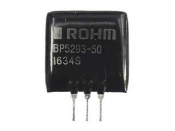
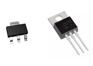
About Linear Regulators
These electronic components are used to easily configure a constant-voltage circuit, generally called a three-terminal regulator. Among these, the type that can operate even with a small difference between input voltage and output voltage (about 1V) is called LDO (Low Drop Out) regulator. LDO regulators are used to create a power supply voltage output that meets microcontroller specifications by using a DC power supply from a switching regulator, DC-DC converter, or USB power supply of a PC as input.
They are called linear regulators because the relationship between input and output is linear, i.e., the output is linear. It is also called a series regulator because it consists of elements that control the load voltage in series between input and output.
Linear regulators generate more heat due to the larger input-output voltage difference, which also results in more loss. However, since they do not perform high-speed switching like switching regulators, they do not generate noise and the output voltage is very stable. In particular, LDOs operate even when the input-output voltage difference is small, making them ideal for MCU power supplies.
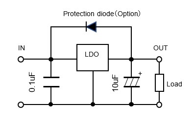
When using the regulator, a capacitor should be added between the input and output pins and GND to stabilize the regulator function.
In some cases, a protection diode may be attached to protect the regulator from destruction by allowing the surge generated on the output side due to some trouble to escape to the input side.
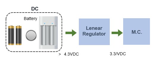
If the microcontroller is to be powered by a battery, either connect it directly to the microcontroller or use only a linear regulator (LDO) to create a microcontroller-specific power supply. The power supply circuit can be configured with only a few components.
About Capacitors
Capacitors are a common component in power supply circuits. There are various types of capacitors in terms of capacitance, withstand voltage, frequency characteristics, etc. For use in power supply circuits, three types of capacitors should be known: aluminum electrolytic capacitors, tantalum electrolytic capacitors, and ceramic capacitors.
In addition to type and capacitance, withstand voltage and frequency characteristics may also be considered in capacitor selection. Parameters such as equivalent resistance ESR and equivalent series inductance ESL are also important, especially for high frequency applications, but are not so critical for microcontroller power supply applications.
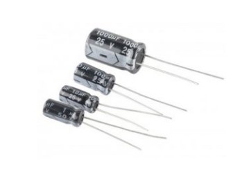
Aluminum electrolytic capacitors are used to reduce large voltage fluctuations with large capacitance. These capacitors have polarity and are available in capacitance and withstand voltage up to quite large capacitance. Care must be taken to avoid rupture if the wrong polarity is used.
Aluminum electrolytic capacitors are used to equalize the voltage in rectifier circuits.
It does not have a very good frequency response, and its large size is a disadvantage.
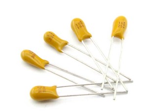
Tantalum electrolytic capacitors are functionally similar to aluminum electrolytic capacitors and are used when a smaller size is required, as surface mount types are available. Like aluminum electrolytic capacitors, these also have polarity.
The advantage of tantalum is its superior frequency response compared to aluminum electrolytic capacitors, but its disadvantage is its relatively high price due to the scarcity of tantalum metal.
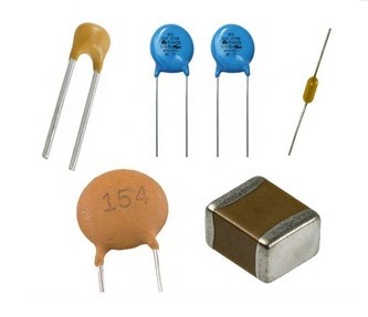
Ceramic capacitors are widely used in applications with relatively small capacitance. Because of their excellent frequency characteristics, they are used for high-frequency noise suppression.
Recently, ceramic capacitors have come to replace aluminum electrolytic capacitors and tantalum electrolytic capacitors because of their relatively large capacitance.
No polarity.
MCU power supply and capacitors
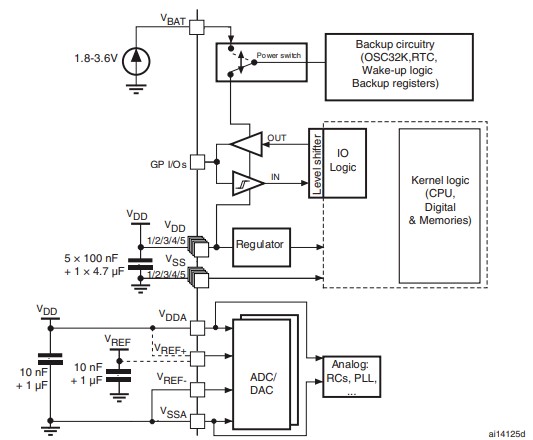
When commercializing a MCU, it is important to stabilize the power supply by placing the capacitors listed in the specifications around the power supply. Capacitors for this purpose are called bypass (decoupling) capacitors.
MCU power supplies are produced through switching regulators, DC-DC converters, and linear regulators, but the actual circuits are complicated with printed patterns and other intricate details. Therefore, even if the MCU is supplied with the power supply voltage according to specifications and theoretically there is no problem, the MCU voltage may be unstable due to various noise effects.
Therefore, capacitors with the capacitance listed in the specifications are placed as close as possible to the power supply terminals of MCU. There are about 5 to 10 pairs of VDD on the positive side and VSS on the GND side, depending on MCU, and ceramic capacitors with good frequency response of about 0.1uF are placed in all pairs to suppress minor fluctuations.
Aluminum electrolytic capacitors, tantalum electrolytic capacitors, or ceramic capacitors of 4.7uF to 10uF are placed at the base of the power supply to suppress large fluctuations.
■ Switching power supply and LDO regulator are required to make power supply for MCU from AC power supply
■ Only an LDO regulator is needed to create a power supply for MCU from a battery
■ If you need a power supply other than for MCU, use a DC-DC converter in the middle.
■ Select components in consideration of capacitance, noise, etc. for power circuit design
■ It is important to select a capacity large enough for the load to be used
■ Understand and use capacitor types and characteristics
Now you understand that a single word "power supply" does not mean simply supplying a specified voltage. There are various types of power supplies, and they must be selected in consideration of capacitance, size, noise, and other factors. This is so important that you should be cautious enough to be a little nervous when designing a power supply for the first time. Incidentally, according to our experience, most MCU equipment problems are power supply related.