Serial communication I2C[I2C details of STM32]

This section explains how to use the STM32's built-in peripheral I2C. This chapter explains how to read and write data to an I2C-specification EEPROM as an example.
Table of contents
What is serial communication I2C?

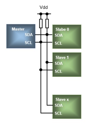
Serial communication I2C is a synchronous bidirectional serial communication method proposed by Philips. It has only two signal lines, one of which is the Serial Data Line (SDA) for bi-directional data exchange and the other is the Serial Clock Line (SCL) for synchronous clock signals.
The characteristic feature is that it is divided into a master side and a slave side, with the master side controlling all communication. I2C allows multiple slaves to be connected to a single bus. The bus is connected by an open drain and requires a pull-up resistor (approximately 2.2k when the supply voltage is 3.3V).
In I2C, one character (one byte) is transmitted and received at a time, and an ACK (acknowledge) signal is returned from the receiving side for each byte transferred, and the transfer is performed while the two sides confirm each other (handshake). When the master wants to terminate the reception, the ACK is not returned as NACK (Not Acknowledged).
Each I2C device has a slave address and accesses registers and memory at the specified address in the slave device to exchange data.
This section explains how to send and receive data using an EEPROM with I2C communication specifications in an actual program.
Since the rules for sending and receiving data using I2C are defined by standards, it is safe to use a certain format by referring to sample programs created by manufacturers.
First, initialization is explained as for other peripherals.
I2C initialization procedure
Purpose: I2C used is I2C1 and GPIOs are PB6 and PB7
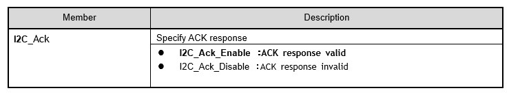
■ I2C : ACK Enable
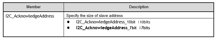
■ Address length to return ACK : 7 bits
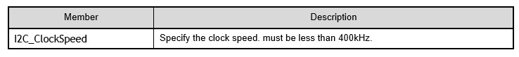
■ Clock speed : 200000 / Duty ratio : 1:1
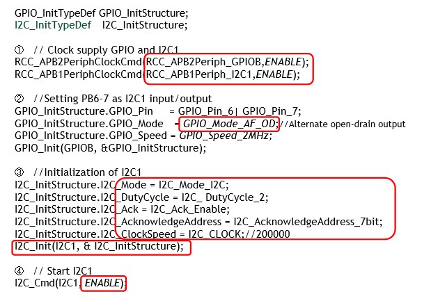
① Clock supply to I2C1
Clock is supplied to I2C1 to be used, which is connected to the APB1 bus, so it is supplied to APB1.
② GPIO settings used for I2C1
The IO used for I2C1 designates PB6 and PB7 as alternate open drain outputs for transmit and receive.
③ I2C1 initialization
Performs initial settings for I2C. Initialization is done by executing I2C_Init() to set the above parameters.
The first argument of the function is the I2C (I2C1, I2C2) to be set, and the second argument is a structure member, as shown below.
Execution Example of I2C initialization function: I2C_Init(I2C1, &I2C_InitStructure);
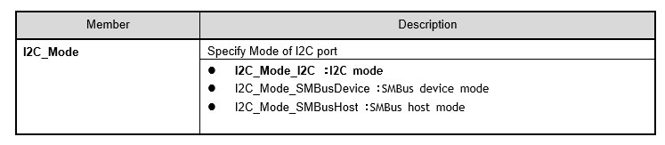
I2C_Mode member specifies I2C mode for I2C.
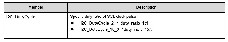
The I2C_DutyCycle member should normally have a clock pulse duty ratio of 1:1. This member is for fast clock waveform shaping and is only valid when the clock frequency is in fast mode.
The I2C_Ack member is set to I2C_Ack_Enable to specify that ACK (acknowledge) is to be returned.
The I2C_AcknowledgeAddress member specifies the slave address width. In accordance with the slave device specification, 7 bits are specified here.
The I2C_ClockSpeed member specifies the clock frequency. Here, I2C_CLOCK(200000) is specified.
The standard mode is automatically selected if the clock frequency is less than 100 kHz, and the fast mode is automatically selected otherwise. 200000 is the fast mode.
④ Enable I2C1
Now that I2C has been initialized, execute I2C_Cmd() to enable the I C port.
Execution Example of I2C activation function : I2C_Cmd(I2C1, ENABLE);
The first argument of the function specifies I2C1 or I2C2 to be set, and the second argument is ENABLE to enable or DISABLE to disable.
I2C type EPROM writing
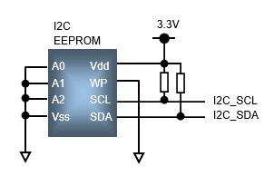
I2C type EEPROM connection circuit
For I2C writing, create and execute the write function I2C_EEPROM_Write() according to the following formatting procedure. Within the function, commands are executed in chronological order.
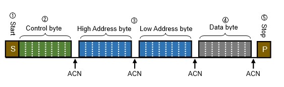
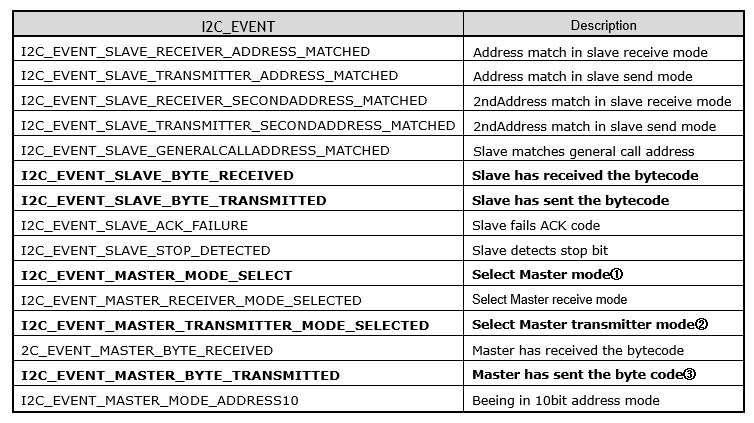
The STM32's I2C generates various events in between data transfers. In the actual program, you will proceed with the procedure while checking the status of the events.
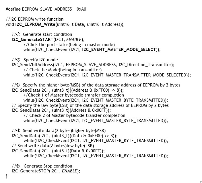
① Start conditions Generation
When the start condition is generated by executing I2C_GenerateSTART(), the device automatically enters master mode and starts communication with the slave side.
Execution Example of I2C_Generate START function: I2C_GenerateSTART(I2C1, ENABLE);
The first argument of the function is the I2C (I2C1, I2C2) to be set, and the second argument is enabled with ENABLE and disabled with DISABLE.
Execution Example of I2C_CheckEvent function:I2C_CheckEvent:
while(!I2C_CheckEvent(I2C1, I2C_EVENT_MASTER_MODE_SELECT));
I2C_CheckEvent() is executed to check if it is in master mode here.
② Specify I2C mode
Here the mode of I2C communication is set: execute I2C_Send7bitAddress() to specify the address and data direction (receive or send) of the slave side (EEPROM).
Execution Example of I2C_Send7bitAddress function:
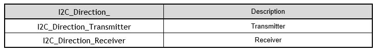
I2C_Send7bitAddress(I2C1, EEPROM_SLAVE_ADDRESS, I2C_Direction_Transmitter);
The first argument of the function is the I2C (I2C1, I2C2) to be set, and the second argument is an 8-bit address, so specify the slave address 7 bits left-justified.
In the circuit employed, the EEPROM address is 1010000 (7 bits) with the upper 4 bits fixed at 1010 and the lower 3 bits at 000 with the designation A0/A1/A2.
This is left-justified and specified as 10100000 (0xA0) (EEPROM_SLAVE_ADDRESS). The third argument is for writing, so specify "Transmitter" for the data direction I2C_Direction. Again, the I2C_CheckEvent function is executed to check whether the device is in transmitter mode or not.
③ Specify 2 bytes of address to store EEPROM data
Specify 2 bytes of address to store data to be written to the I2C slave side (EEPROM) by executing I2C_SendData() and dividing it into upper and lower addresses.
Execution Example of I2C_SendData function:
I2C_SendData(I2C1, (uint8_t)((Address & 0xFF00) >> 8)); //Upper address
I2C_SendData(I2C1, (uint8_t)(Address & 0x00FF)); //Lower address
The first argument of the function specifies the I2C (I2C1, I2C2) to be set, and the second argument specifies the 2-byte address where the data is stored. The address range depends on the capacity of each EEPROM, so check the datasheet and specify the available range.
Execution Example of I2C_CheckEvent function:
while(!I2C_CheckEvent(I2C1, I2C_EVENT_MASTER_BYTE_TRANSMITTED);
④ Send write data (2 bytes) to EEPROM
Transfers the data to be written to EEPRON to the data register. As with the address transfer in (3), data is transferred separately to the upper and lower registers.
⑤ Stop Condition Generation
Stop conditions are generated by executing I2C_GenerateSTOP(). The first argument of the function is the I2C (I2C1, I2C2) to be set, and the second argument is enabled with ENABLE and disabled with DISABLE.
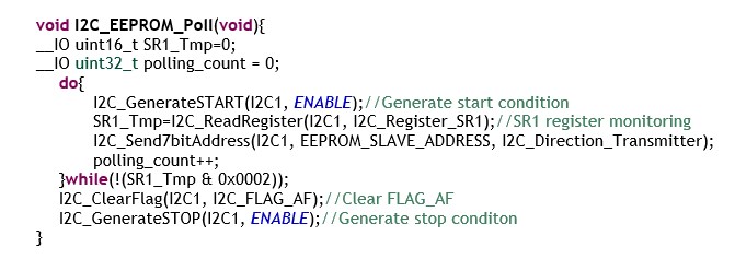
I2C_EEPROM_Poll function
Writing to EEPROM starts after executing the aforementioned write function and generating a stop condition. writing to EEPROM takes some time, so in order to write data continuously, the next data must be written after confirming that data transfer is completed. The following is an example of a case in which the use of a single device is not recommended.
For this process, the I2C_EEPROM_Poll function created by the STM32 manufacturer is used, and it is executed in combination with the I2C_EEPROM_Write function when writing EEPROM.
Execution example of sending DATA (16 bits) to the EEPROM address ADDRESS (2 bytes):
I2C_EEPROM_Write(DATA, ADDRESS);
I2C_EEPROM_Poll();
I2C type EEPROM read
For I2C read, create and execute the read function I2C_EEPROM_Read() according to the following formatting procedure. This function returns data given the address where specific data is stored in the EEPROM.
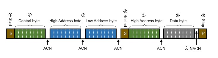
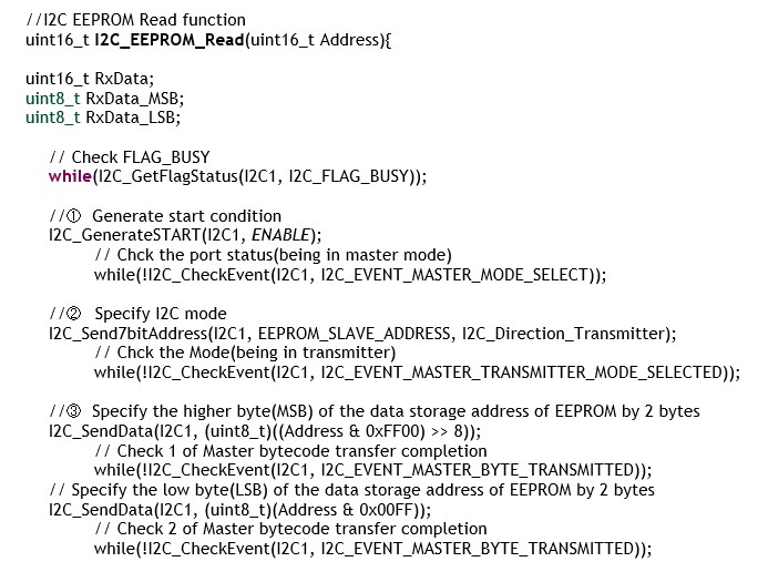
In the case of reading, check to see if the I2C bus is free in advance before starting the procedure.
Steps (1) through (3) are the same as for the write function. Here, specify the address where the data to be read is stored. Up to this point, I have been using the transmit mode to specify the address.
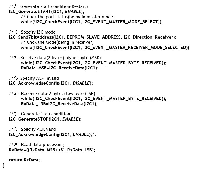
④ Generation Start condition (Restart)
From here, the start condition is generated again for switching to receive data at the specified address.
⑤ Specify I2C mode
To set the I2C communication mode to receive, execute I2C_Send7bitAddress(). As in (2), the second argument is the slave address and the third argument is the data direction I2C_Direction (Receiver) since it is a case of reading. Again, I2C_CheckEvent() is executed to check if it is in the receive mode.
⑥ Receive read data
When ready to receive data, I2C_CheckEvent() is executed to confirm the completion of data transfer in the receive register, followed by 2-byte data for the upper 1 byte and the lower 1 byte.
⑦ ACK disabled
Since we want to terminate the reception at this point, we disable ACK in I2C_AcknowledgeConfig() to make it NACK (Not Acknowledged) without returning ACK. In this example, the function is executed before the last byte (for the lower byte) of the 2-byte data to be received is received and returns NACK.
⑧ Stop condition Generation
Generates stop condition.
⑨ ACK enabled
Return ACK to validity for the next communication.
⑩ Readout data processing
The data is processed from the received upper and lower data into 2-byte data, which is the return value of the read function I2C_EEPROM_Read().
I2C is one of the more delicate of the peripherals, and you may get stuck using the library functions as a black box; checking the behavior of the library functions to the STM32 reference manual is a quick and crushing way to understand them.
See "I2C communication application [I2C of STM32]"and "Posture detection by accelerometer and gyro sensor [STM32Nucleo]" about the practical application with I2C EEPROM.