Posture detection by accelerometer and gyro sensor [STM32Nucleo]
The GY-521 Sensor Board with Accelerometer and Gyro Sensor (MPU-6050) can easily acquire 3-axis acceleration and 3-axis gyro data via I2C interface, and is recommended for its high information content and low cost.
However, most of the information on the Internet is for Arduino, and while the programming can be easily utilized by anyone using existing library functions and can be made to work without understanding the specifications, it is not a skill that can be acquired because it can be used somehow.
Therefore, this article will explain how to grasp the main points from the specification sheet of the acceleration sensor and gyro sensor (MPU-6050) and how to use it while keeping the basics of I2C communication in mind.
Table of contents
Acceleration and Gyro Sensor Board

Since it is quite complicated to calculate the X-, Y-, and Z-axis tilt angles from scratch, this article explains how to calculate the tilt angle around one axis (Y-axis) from the acceleration sensor and gyro sensor.
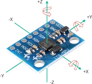
In MPU-6050, the X, Y, and Z axes are set in the orientation shown in the figure below.
Acceleration data
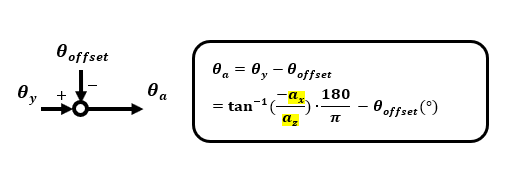
When an accelerometer is used to tilt θy around the Y-axis, the tilt angle θy can be calculated using an inverse trigonometric function based on the gravity ratios in the Z-axis and X-axis directions.
As explained in "Accelerometer using STM32 Nucleo", the values ax, ay, az in each axis due to the gravity (1G) component of the acceleration sensor are the direction of drag force against gravity. As shown in the figure below, when the coordinates are inclined positively θY around the Y axis, the drag force az for the gravity Z axis component (1GZ) is a positive value and the drag force ax for the X axis component (1GX) is a negative value.
Since acceleration due to motion is not considered here, the calculated data is the angle (absolute angle) in static state inclined with respect to the ground.

If the offset θoffset is subtracted from the calculated absolute angle, the angle can be preset to the reference 0° at any angle, so it can be made relative to the reference. Angles when using inverse trigonometric functions are converted to ° if necessary, since the unit is rad.
Gyro sensor data
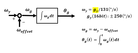
In the case of a gyro sensor, the data gy is the angular velocity during rotation around the Y-axis, so the angular velocity must be integrated and calculated in the program to obtain the angle.
First, the obtained 16-bit data is converted to angular velocity (°/s) according to the scale. Then, if there is an offset, it is subtracted beforehand and integrated to calculate the angle.
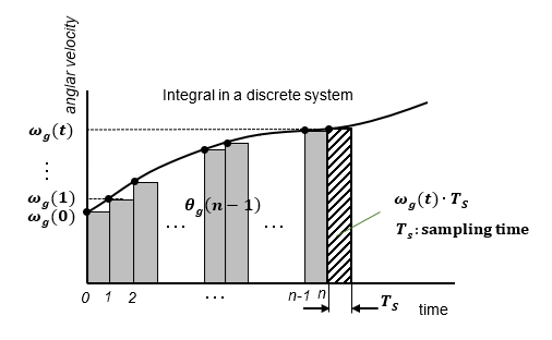
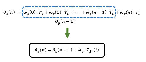
Integration within the program is a discretized approximation. The simplest integration is the algorithm shown below. If the sampling time Ts is small enough, this will not be a problem.
In the case of a gyro sensor, the angle is calculated by integrating the angular velocity, so if the offset exists in the initial stationary state and is not 0°/s, the error will accumulate to a large degree. Therefore, if the offset is subtracted beforehand, the angular drift will be improved.
Wiring diagram between MPU-6050 and Nucleo board
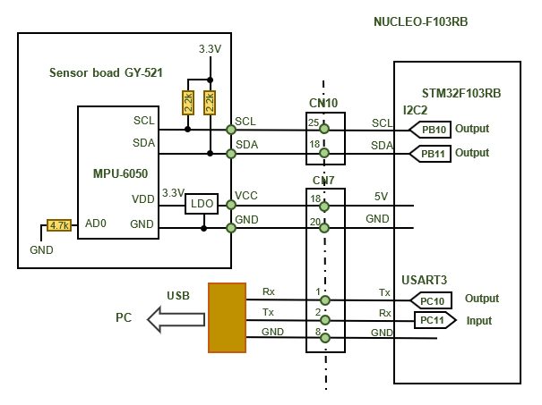
The figure below shows an example of wiring when MPU-6050 is connected to Nucleo-F103RB.
Connect 5 V to the power supply of the sensor board GY-521, which has a built-in LDO regulator.
The data output interface is connected to I2C2 on the STM32 side for I2C communication. I2C I/O is set to open drain, so a pull-up resistor is normally required, but the GY-521 sensor board includes one beforehand.
Data calculation by programming
The first step is to successfully set up I2C communication and read/write data. Once data can be read arbitrarily and stably, all that remains is to calculate the angle by computing the data in the manner described so far.
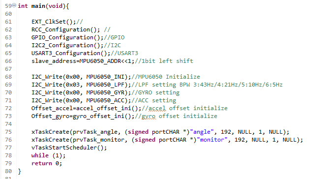
To use an I2C communication device, the initial configuration is first done in I2C2_Configuration(). This is the same as for any other I2C device. For details, see "Serial communication I2C[I2C details of STM32]".
After the initial setting of I2C2, the MPU-6050 is configured. The settings are made by writing values to registers. This is not necessary if you use all default settings, but it is necessary if you use the device's built-in digital filter or if you want to change the full scale of data.
I2C setting and data write/read
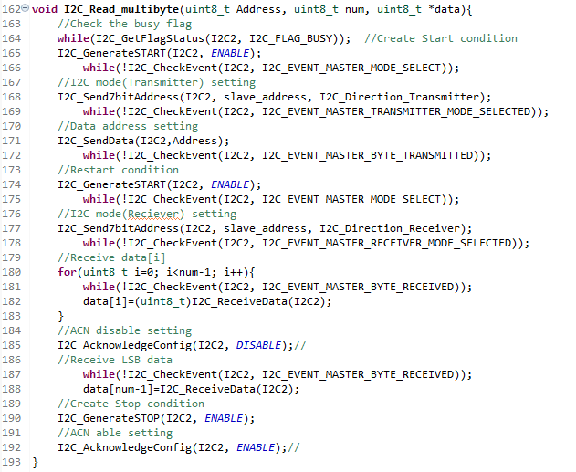
In I2C communication, data is read and written in 1-byte units, but it is more efficient to read multiple bytes of data at once, rather than reading individual bytes of data by itself.
Then the read data address only needs to read 14 bytes from the accelerometer's X-axis data address 3B and store the data in an array.
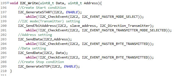
As we will discuss later, I will create our own function to write one byte of data to the desired register.
The key point here is the slave address. In the I2C address send function I2C_Send7bitAddress(), the address is left-justified 7 bits in a 1-byte frame. It is handled as 1-byte data with a send or receive flag added to the least significant bit.
You can understand this by checking the contents of the library functions and following their operation.
For example, if the slave address of an I2C device is 0x68, 0xD0, shifted left by 1 bit, is the address given to the send function I2C_Send7bitAddress().
Data reading is like an extension of writing, but multiple bytes of data can also be read in succession.
This is also a multiple byte read function of my own making, but the key point is that if there is more than one data, it should be NACK, which does not return ACK just before the last byte data is received.
Initial settings for MPU-6050
The MPU-6050 initially sets the clock source to the sensor in a register, the full scale of the accelerometer and gyro sensor, and the filter to the output.
If you only want to acquire angles with the accelerometer and gyro sensor, you can use the default settings, but the registers to be handled are the following at most.
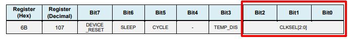
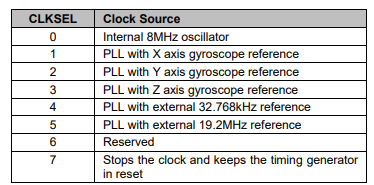
Specify clock source
The MPU-6050 begins functioning by specifying the clock source. The clock source is set in the lower 3 bits of register address 6B. The default clock source at power-on is 8 MHz internal oscillation.
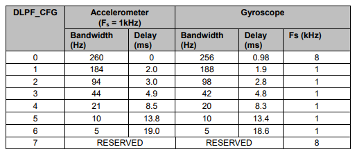
Specifying Filters
The MPU-6050 can be configured with a low-pass filter for noise suppression on the output. Set a value from 0 to 6 in the lower 3 bits of register address 1A as required.

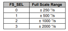
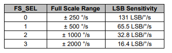
Specify gyro sensor scale
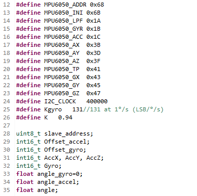
Register address 1B sets the gyro sensor full scale with a value from 0 to 3. The default is ±250°/s.

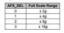
Specify Accelerometer Scale
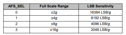
Register address 1C sets the accelerometer full scale with a value from 0 to 3. The default is ±2g.

Reading Accelerometer Data
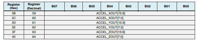
The data for each axis of the accelerometer is 16 bits, but the data storage address is 8 bits, so it consists of the upper 8 bits and the lower 8 bits. The X-, Y-, and Z-axis data are stored from register address 3B in the order of X-axis upper, lower..., and so on.
For data, for example, if the full scale is ±2g, the value is 32768 at +2g, which is 16384 per G.
Reading gyro sensor data
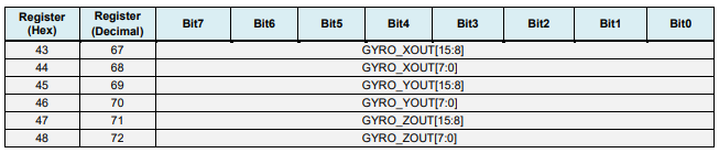
As with the accelerometer, the X-, Y-, and Z-axis data for each axis of the gyro-sensor is also stored in register address 43, starting with the X-axis upper, lower, and so on. The data for each axis of the gyro sensor is stored in the same order as for the acceleration sensor.
For example, if the full scale is ±250°/s, the data is 32768 at +250°/s, which is 131 per 1°/s.
Angle calculation from each sensor and complementary filter
Once the data from the acceleration and gyro sensors is available, the angle can be calculated from each of the data.
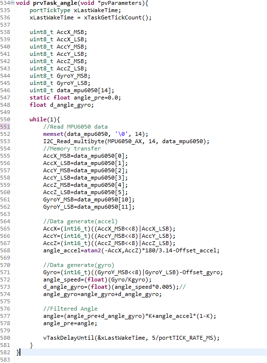
The data stored by reading multiple bytes with the I2C_Read_multibyte() function can be used to obtain 16-bit values for each axis of the acceleration and gyro sensors.
The angle from the acceleration sensor and the angle from the gyro sensor can be calculated based on the obtained values.
The RTOS function is used to ensure that the sampling time for integrating the angular rate data from the gyro sensor to calculate the angle is exactly 5 ms. See "FreeRTOS task management basics".
Angles calculated independently from the accelerometer and gyro sensor have their own advantages and disadvantages, and are not stable. Therefore, a complementary filter is used to combine the advantages of both sensors.
Accelerometers provide the tilt angle due to changes in gravity, so the absolute angle change is reliable, especially in static state, but the information may contain noise, and if motion is involved, components other than gravity may also be added.
In contrast, a gyro sensor provides an angular velocity that detects rotation, so it is reliable for the angular change that accompanies movement, but because it integrates within the program, errors accumulate at the same time, causing drift.
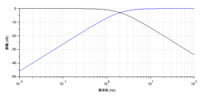
Therefore, a complementary filter can be used: a low-pulse filter (LPF) is used for the accelerometer output to take out only the low-frequency portion, and a high-pass filter (HPF) is used for the gyro sensor output to cancel out the drift portion.
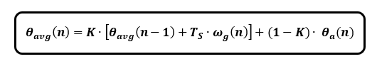
Looking at the complementary filter formula alone, it is quite simple, but it is very deep and is explained in detail in a separate article, "Let's clarify the mechanism of the complementary filter [acceleration/gyro sensor]".
Measured results
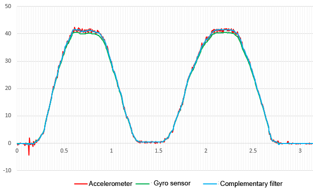
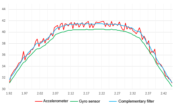
The figure below graphically illustrates the angle change resulting from the output through the accelerometer, gyro sensor, and complementary filter. The horizontal axis is elapsed time (s) and the vertical axis is angle (°).
The angle from the accelerometer contains fine noise but shows an absolute angle, so no drift occurs.
The angle from the gyro sensor is integrated in the program, so it is smooth and without noise, but there is a drift due to cumulative error.
The output through the complementary filter is stable and reliable because it inherits only the advantages of the output from the accelerometer and the gyro sensor. The cutoff frequency of the complementary filter is set at 2 Hz.
To see what difference there is depending on the cutoff frequency of the complementary filter, I compared it at 4Hz and 2Hz.
When the cutoff frequency is set to 4 Hz, there is no effect of drift due to the gyro sensor, but there is some sensitive noise component from the accelerometer. The output is affected by the accelerometer.
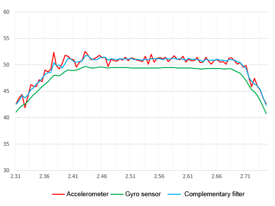
When the cutoff frequency is set to 2Hz, the noise component of the accelerometer is almost cancelled out and the output is influenced by the gyro sensor. The output is the result of canceling only the drift component of the gyro sensor output.
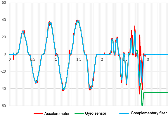
The figure below shows the output results of a slightly faster operation with a cutoff frequency of 2 Hz.
The accelerometer cannot be used as it is because the faster the movement, the more noticeable the noise component becomes, and the gyro sensor cannot be used as it is because the offset due to the drift component suddenly becomes large.
In contrast, the output through the complementary filter does not show any delay in such an operation, but follows the signal firmly and is almost in an ideal state without any drift effect, confirming the filter effect.
I explained the process of connecting the inexpensive and popular GY-521 (MPU-6050) sensor board to an STM32Nucleo board to calculate the angle of inclination. You may think that this is just for angle calculation, but when you go this far to check the operation, there is no ambiguity at all, and you can confidently apply the knowledge you have gained to other applications as a new skill.
Now that we have a means of acquiring angle and angular velocity on the STM32Nucleo, we finally have the tools to realize an inverted pendulum. We have explained the control of the inverted pendulum using modern control theory in "Fundamentals for Feedback Control realized by MCU [Extra Edition]" and we will try to realize it on an actual device in the near future.