Basic knowledge around Microcontroller for Embedded engineers [must-see for beginners]
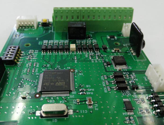
Table of contents
Hardware and Software around MCU
What is the configuration of the MCU itself and what functions does it have?

Before computers existed, the world around us was all about hardware. In the case of electrical products, such as televisions, all functions were composed of electrical and electronic circuit hardware. The same is true for automobiles. Everything was composed of hardware mechanical parts.
With the advent of computers came the concept of software.
Computers take analog (physical) things in nature, such as the intensity of light or the volume of sound, through input devices such as sensors, convert them into digital form internally, and then add various functions through computer programs and output them in the required form.
This computer program is what we call software. It does not have a form like hardware.
Therefore, the smaller the size of a computer, the smaller it becomes and the fewer mechanical parts it has than a computer consisting only of hardware with the same functionality, resulting in fewer failures, easier mass production, and lower prices.
MCU (microcontroller) is a computer specialized for controlling electrical devices, and in addition to the CPU, which serves as the brain, it has built-in analog and digital signal input/output, timer/counter, and serial communication functions, allowing developers to easily develop sophisticated electrical devices by simply adding the minimum necessary interface circuits between the actual input and output signals.
The functionality is created by a program called software. This is where the programmer's skills really come into play. Therefore, MCU programmers need not only knowledge of programming languages, but also knowledge and experience of microcontroller functions, peripheral circuits (interfaces), and other hardware.
Hardware knowledge is not what it used to be, and the Internet provides a great deal of information. Using this knowledge to actually build your own hardware circuits is a shortcut to a deeper understanding.
Embedded skills will not be acquired or useful at all if you only deal with software (programming) and do not know the real thing (hardware).
The real appeal of embedded systems is to improve the degree of perfection while actually programming and measuring inputs and outputs.
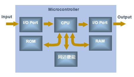
Basic Structure of MCU
MCU consists of CPU, ROM, RAM, I/O ports, and various other functions.
CPU :
The brain of MCU executes program commands to perform calculations and realize functions.
ROM :
The memory is Read-Only Memory, which stores programs and data such as constants that do not need to be changed during execution. The data is not lost when the power is turned off, and the program is read and executed after the microcontroller starts up.
RAM :
A part of memory that is read/write (Randam Accessy Memory) and stores data (variables) temporarily. The contents are also lost when the power is turned off.
IO port :
This is the part (terminal) that performs the function of reading signals between the MCU and external components. I is Input and O is Output.
Peripherals :
MCUs contain various functions (hardware circuits) used in applications, such as AD/DA converters, timer/counters, and serial communications. They are called peripherals.
Registers and memory (a bit technical)
Registers are special memories mainly used to store and check the state of the MCU; CPU registers are used to store and check the state of the CPU.
Specifically, registers are used to store data during operations, return addresses when the program branches off due to interrupts or subroutines, information when the result of an operation is negative or zero, and carry-over values.
CPU general-purpose registers are directly connected to the CPU by hardware, allowing faster access than RAM, which accesses data via an internal bus.
The control registers for peripheral functions are used to set I/O ports called general-purpose I/O GPIOs, timers, serial communications, AD converters, DA converters, and other peripheral functions.
There are status registers that indicate the status of peripheral functions, result registers that store the conversion results of AD converters, and transmit/receive data registers that store transmit/receive data in communication functions.
Although it is possible to set registers directly from the program, usually the firmware library (device driver) provided by the manufacturer is used, so registers are set indirectly, without direct awareness.
However, it is recommended to look over each register described in the specifications when you have a certain level of understanding of the device. See "How to read the ARM STM32 register map".
Introduction of peripheral functions built into MCU
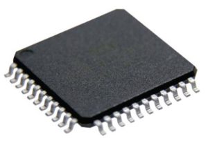
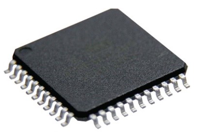
MCUs have many legs (pins). If you look at the data sheet of a microcontroller, you will see that various functions are assigned to each pin.
Various functions are general-purpose I/O ports, AD/DA converters, timer/counters, serial communications, and other useful functions used in applications.
Since the number of pins in a MCU is limited, multiple functions can be assigned to a single pin, allowing the software to select the function to be used.
The various functions are introduced below so that you can understand the concept of each.
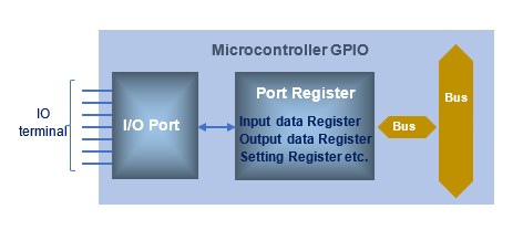
GPIO :
An input (I) port is used to input some kind of signal such as a switch or sensor, and an output (O) port is used to provide an output to drive a load such as an LED. A port is a pin (terminal) that serves as an input/output window, also called GPIO(General Purpose Input/Output).
GPIO is sometimes abbreviated as "PA1" in reference manuals and drawings; PA1 means "the first pin of GPIO port A".
Input and output ports are often used concurrently and can be switched by register settings. GPIO is a digital input/output port, so it determines 0 or 1 depending on the input voltage in case of input, and gives 0 or 1 status in case of output.
For a MCU with a supply voltage of 3.3 V, the upper reference value of approximately 2 V or higher is H level, and the lower reference value of approximately 0.8 V or lower is L level. Normally, a MCU expresses a H level as 1 and a L level as 0. 1 at a H level and 0 at a L level are called positive logic, and 0 at a H level and 1 at a L level are called negative logic. When writing programs, this logic is often inverted for outputs and so on.
Some I/O ports can handle analog signals. Since the number of ports (pins) that can be used is limited, allocation should be made by carefully checking the specifications during the design stage.
Please refer to "General-purpose Input/Output [Details of STM32 GPIO usage]" for the STM32 GPIOs used in this site.
Timer/Counter :
A signal with a fixed period generated by a clock generator such as a crystal oscillator is called a system clock. A timer/counter, a peripheral function, is a combination of a clock signal generated by arbitrarily dividing this system clock and a counter.
Frequency dividing means that when the clock frequency is high, for example, a 1 MHz clock is reduced by 1/1000 to a 1 kHz clock.
A clock (clock pulse) is simply a digital signal that repeats H and L levels in a fixed cycle. MCU's timer counter function automatically counts the clock and notifies the user after a set elapsed time.
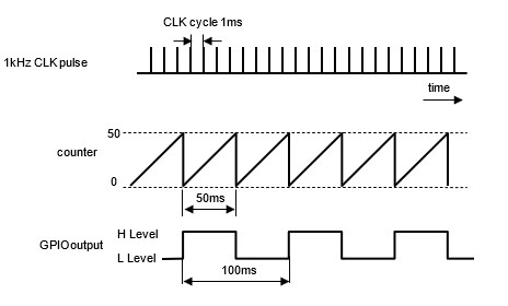
Let's look at an example of signal output using a timer counter. This example uses a clock divided by 1 kHz for the timer to produce an arbitrary constant interval output.
Here an up counter is used to count the clock. The up counter counts the input clock (pulses) from 0 to a set value in the direction of increasing the clock, and when the set value is reached, it returns to 0 and repeats the count again.
This is an example of inverting the output state (in this case, switching the H and L levels) as a notification when the set value is reached.
The clock cycle is 1 ms, so if 50 is set for the counter, the count value is reached and then reset every 50 ms repeatedly. In this example, the output state is reversed each time the counter is reset, resulting in a pulse output of 100ms cycle.
Although we have used a timer counter as an example of signal output, all time-related processes in your application can be realized with a timer counter.
Timers/counters are hardware circuits independent of the CPU, so they can perform advanced processing without burdening the CPU. Among timer functions, some MCUs have a PWM function, which is useful for a wide range of applications (PWM will be explained in detail later).
Please refer to "Timer/Counter[STM32 Timers Details]" for the STM32 timers used in this site.
AD converter :
Normally, GPIO input is digital and only determines whether the voltage is a 1 or 0, but some ports can handle analog signals, allowing the use of an AD converter function. Since the number of available ports (pins) is limited, it is only necessary to assign them while carefully checking the specifications in the design stage and setting the input port specifications to analog signal input.
The AD converter (Analog-to-Digital conversion) reads analog signal voltage at the range level determined by MCU specifications from the input port and converts it to a digital value using a method set inside MCU.
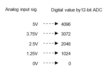
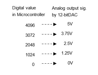
For example, if a 0-5V analog signal is input to an AD converter with a maximum input voltage of 5V and 12-bit resolution, the resolution is 4096 (212), resulting in 4096 digital data when the input is 5V. At half 2.5V, it is 2048. In this way, the analog signal has been digitized within the resolution range in MCU and can be handled as a numerical value.
Although MCUs themselves handle digital signals, there are many applications in which they handle analog signals such as sound, light, and temperature.
The AD converter is an indispensable function that converts analog signals into digital signals that can be processed by the MCU.
Please refer to "AD converter [ADC details of STM32]" for the AD converter of STM32 used in this site.
DA converter :
A DA converter (Digital-Analog conversion) is the reverse of an AD converter and converts digital values in a MCU into analog signals for output. For example, if you want to output an audio signal, you need to represent the waveform of the audio, and the waveform is exactly a continuous analog signal.MCUA DA converter (Digital-Analog conversion) is the reverse of an AD converter and converts digital values in a MCU into analog signals for output. For example, if you want to output an audio signal, you need to represent the waveform of the audio, and the waveform is exactly a continuous analog signal.
A DA converter is used to output such analog signals. A DA converter with an output reference voltage of 5 V and a resolution of 12 bits will divide the reference voltage into 4096 (212) equal parts and output one of the voltages. For example, the output is 5 V when the digital value is 4096, and 2.5 V when the value is half of 2048.
Thus, a DA converter can output the digitized values in the MCU as analog signals.
Serial communication :
MCUs, for example, have a serial communication function that transmits data sequentially in a straight line, as opposed to parallel communication that transmits 8-bit data at a time through multiple (8) terminals. When communicating the character string "ABC," each character is transmitted simultaneously in parallel communication, whereas in serial communication, each character is transmitted sequentially from 'A' to 'B C', 'C', and so on, one character at a time.
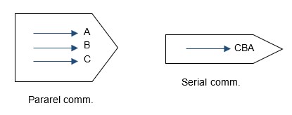
Serial communication does not depend on the number of bits of data to be transmitted, so the number of pins is small.
Among serial communications, asynchronous (asynchronous) UART communications, in which data is transmitted between "start bits" (meaning the beginning) and "stop bits" (meaning the end), requires no synchronization signal and is commonly used in interfaces for monitoring equipment and wireless LAN modules.
USART communication is a development of UART that also supports synchronous communication, and MCUs have built-in USART communication as a peripheral. RS232C, RS485, and RS422, which are commonly used in industrial equipment, have different signal level standards, but they are similar. These can be used by adding a level conversion IC as an external circuit.
Clock-synchronized serial communications requiring synchronous signals include I2C and SPI communications, which are often used for interfaces such as EEPROMs.
Using a UART-USB conversion cable, the device can also be connected to a PC for easy operation and monitoring by creating free serial terminal software or dedicated applications. USART communication can be used for a wide variety of applications, so it is a function that should be mastered by all.
Please refer to "Serial communication USART [USART details of STM32]" for USART communication of STM32 used in this site, "Serial communication I2C[I2C details of STM32]" for I2C communication, and "Serial communication SPC [SPI details of STM32]" for SPI communication.
Interrupt :
The concept of interrupts is essential for embedded control.
For example, if interrupts are not used to detect irregularly input external signals or notifications such as completion of reception in USART communications, etc., the input of such signals and notifications of function completion must always be checked periodically. With interrupts, programs can be simplified and power consumption can be reduced because interrupts can be processed only when some process (event) occurs.
Each peripheral, such as a timer and serial communication, has many functions called interrupt events. Whenever a hardware interrupt occurs, a functional block that describes the processing called an interrupt handler is called and the interrupt processing is executed.
If interrupts are not used, the system periodically monitors events that occur using a method called polling and processes them as necessary. Although this method is easy to implement using only software, it has the disadvantage of delaying the processing timing in addition to the inefficiency of periodically monitoring events that may occur at any given moment. In addition, events that occur outside the polling monitoring period cannot be handled.
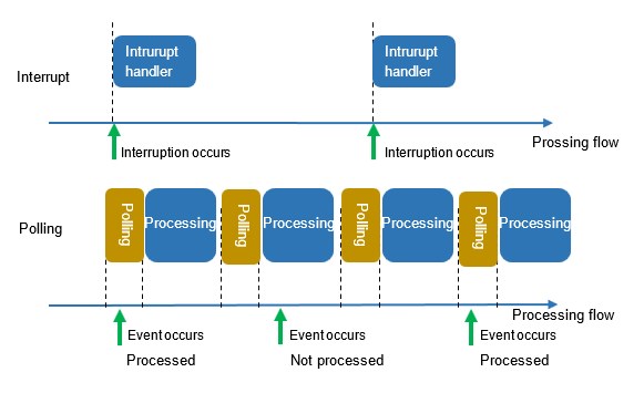
Polling processing is suitable for events that occur regularly and frequently, while hardware interrupts are suitable for events that occur infrequently and need to be processed with strict timing. A well-balanced system can be constructed by using different types of interrupts according to the application.
Please refer to "Various Interrupts [Details of STM32 Interrupts]" for the STM32 interrupts used in this site.
DMA :
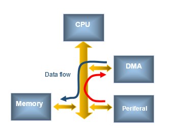
DMA stands for Direct Memory Access and is a function that directly transfers data between peripheral functions (AD converter, UART communication, etc.) and memory (ROM, RAM) through the bus without using the CPU.
Normally, data transfer is performed by the CPU, but in MCUs equipped with DMA, DMA transfers data in place of the CPU.
Therefore, the CPU only needs to perform tasks that can only be done by the CPU, such as arithmetic operations. The DMA reduces the burden (power consumption) on MCU and raises its performance.
It is effective when used in combination with peripheral functions such as AD converters and UART communication. The DMA function should be used aggressively when handling large amounts of data in communication, such as image and audio transfers.
Although the DMA function is not essential for creating MCU applications, it can be utilized to reduce the CPU load and further improve application performance.
The combination with DMA is indispensable for applications using AD converters where signals are to be captured on multiple channels.
This site explains how to use DMA in the peripheral functions of "Serial communication USART [USART details of STM32]" and "AD converter [ADC details of STM32]".
Basic circuit that each pin is composed of
Although MCU has many different functions, the circuitry that makes up each pin is almost the same: functions are assigned by setting registers on the I/O ports (GPIOs). I will discuss each of these functions in detail later, so let's skip this section and focus on "Basic hardware circuits around Microcontroller [Must-see for beginners]".
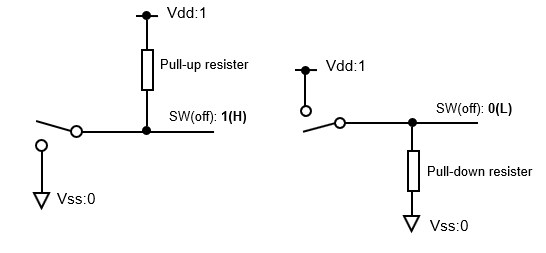
Input pull-up/pull-down resistor :
When the pin is defined as a general-purpose input port, there are two types of inputs: 1 (HIGH) when the power supply voltage Vdd is applied, and 0 (LOW) when it is connected to Vss (GND) and 0V. These are so-called digital inputs.
Input pull-up and pull-down resistors are necessary to input external signals such as switches and sensors to the MCU. Without a pull-up or pull-down resistor, the input would be "floating," meaning that it is neither 0 (low) nor 1 (high). If there is no pull-up or pull-down resistor, the input is susceptible to noise, which can cause malfunctions.
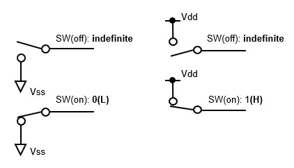
The one to fix to 1 without input is an input pull-up resistor, and the one to fix to 0 is an input pull-down resistor.
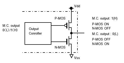
Push-pull output(voltage out)/Open-drain output :
When the pin is defined as a general-purpose output port, the output switches to a circuit consisting of a switching device called a C-MOS, which drives the load with an ON or OFF digital output. For example, if the load is an LED, it switches the LED on and off.
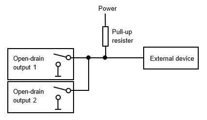
Outputs are available in push-pull and open-drain types.
A push-pull type is one in which the output pin is Vss (GND) when the MCU specifies the output as 0 (Low) and the supply voltage Vdd when the MCU specifies the output as 1 (High).
An open drain type is one in which the output pin is Vss (GND) when the MCU designates the output as 0 (L) and neither the supply voltage Vdd nor Vss (GND) when it is 1 (H).
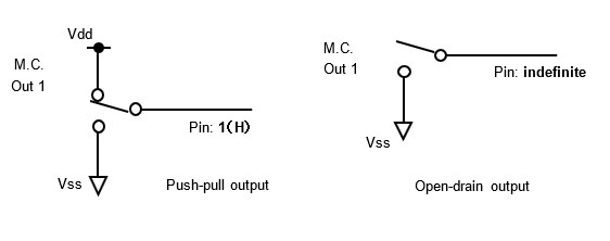
Normally, push-pull outputs are used, but open drain is used for voltage level conversion of output logic or as a wired OR. C-MOS outputs cannot be connected to each other to prevent shorts, but open-drain outputs can be connected as a wired OR because they do not short.
When another power supply is connected to the open drain output via a pull-up resistor, the voltage level is converted to the level of the other power supply.
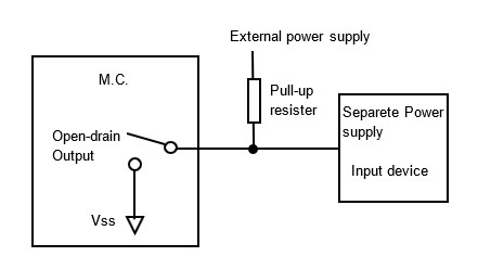
A wired OR is an actual wiring that has the same function as an OR in a logic circuit.
C-MOS is called Complementary MOS and is a type of switching device in logic circuits that combines P-type and N-type MOSFETs in a complementary manner.
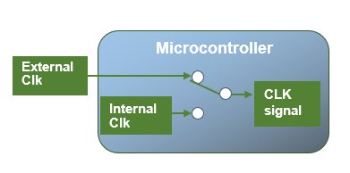
System clock :
There are two types of MCU clock signals to make System clock: the external clock type supplied from an external oscillation circuit such as a crystal oscillator, and an internal clock type supplied from the RC oscillation circuit (internal oscillation circuit) built into the MCU without external components. The internal clock type has the advantage of cost reduction due to fewer external components.
However, the internal oscillation circuit is somewhat less stable in frequency than an external crystal unit due to variations in accuracy.
When designing a system for equipment that requires timing matching with external devices such as UART communications, it is recommended to use an external oscillator with a stable frequency.
When actually selecting a crystal unit at the design stage, it is strictly speaking necessary to check the operation at the prototype stage because of compatibility with the microcontroller.
Based on this clock signal source, each peripheral function such as timers, AD converters, and UART communications are set to a clock that has an appropriately divided frequency. If the system clock source is left as it is, the frequency is too high for each peripheral function such as timers, AD converters, and UART communications, so setting the clock to an appropriately divided frequency and controlling the clock can also save power consumption.
Program Flow
Immediately after power-on, MCU sequentially executes the programs written in memory from the start position.
The execution procedure includes, for example, initial settings, port definitions, and definitions of peripherals to be used.
When ready, the application process is periodically repeated in what is called the main loop. This cycle of repetition is called the cycle time of the program.
Multiple processes required for various applications are executed sequentially and repeated at each cycle time. The cycle time varies depending on the contents of the process. For relatively simple applications, this is fine.
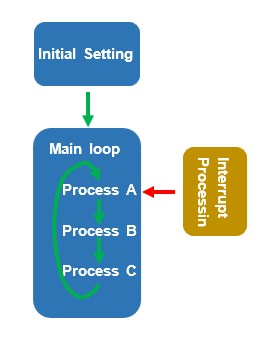
When an interrupt signal is given periodically from an external source, a processing block called a subroutine or interrupt handler can be made to run at a fixed interval. Using an operating system (OS), which will be explained later, it is also possible to divide each process into blocks called tasks, which are periodically prioritized for execution.
Processes that calculate speed, such as motor control, should be relatively fast and have a short cycle time (10 ms or less), but longer ones are acceptable for monitor displays (100 ms or so).
Using an OS is an essential skill for embedded systems, as it allows for efficient program organization in applications where various processes are intricately intertwined.